


80-4280-10, Rev. 4
43
R
1
1
1
FWD
STAT
REV
PWR
SERIAL
PORT
TP3
RIBBON
CABLE
CONNECTOR
TP2
TP1
TP4
MOUNTING SCREWS (4 places)
WIRING CONNECTORS
DCM
FUSES
LOCAL
PUSHBUTTON
INTERFACE
STATUS
INDICATION
LEDs
OVERVIEW
LEDs
CALIBRATE
SET POS
100%
SET POS
0%
SET DEM
100%
SET DEM
0%
DEMAND
POSITION
TORQUE
STALL
TEMP °F
FB OPEN
UVOLT
ACKNOWLEDGE
J5
J2
J4
J3A
J3B
F1
F2
J5
TB1
TB2
TB3
TB4
TB5
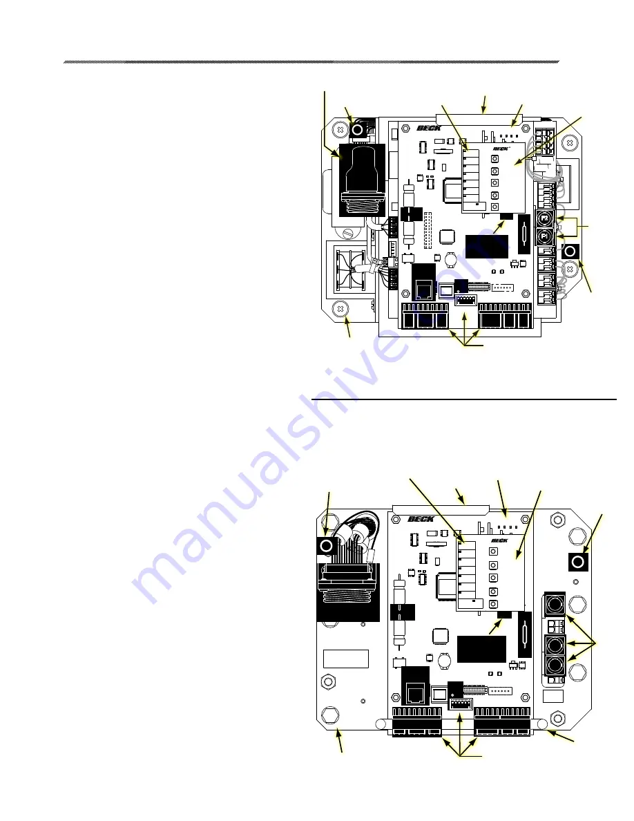
12-8224-41
WIRING CONNECTOR
LOCATING PIN HOLE
LOCATING
PIN HOLE
HANDLE
WIRING CONNECTORS
TP1
FUSES
8 AMP
12-8224-51
J4
J3A
J3B
TP4
J5
FWD
STAT
REV
PWR
CALIBRATE
SET POS
100%
SET POS
0%
SET DEM
100%
SET DEM
0%
DEMAND
POSITION
TORQUE
STALL
TEMP °F
FB OPEN
UVOLT
ACKNOWLEDGE
F1
F2
F3
TP3
RIBBON
CABLE
CONNECTOR
TP2
SERIAL
PORT
WIRING
CONNECTOR
HANDLE
HANDLE
LOCATING
PIN HOLE
LOCATING
PIN HOLE
TP4
DCM
FUSES
LOCAL
PUSHBUTTON
INTERFACE
STATUS INDICATION
LEDs
OVERVIEW
LEDs
MOUNTING SCREWS (6 places)
22-309 DCM-2 CHASSIS
22-409 DCM-2 CHASSIS
Install the new DCM assembly (continued):
4. Reconnect the (5) wiring connectors.
5. Reconnect power to the actuator.
6. Ensure that the DCM is configured properly.
7. Check the state of the LEDs on the DCM. If
either the FWD or REV LED is lit, the actuator
will reposition when the Handswitch is returned
to AUTO. If desired, change the Demand
signal or reposition the actuator using the
Handwheel or hand crank until both the FWD
and REV LEDs are out. When both LEDs are
out, the actuator Demand and position are
balanced and the Handswitch can be returned
to AUTO.
Check actuator calibration:
Ensure that the actuator calibration is correct by
verifying the parameters listed in Table 2 match the
parameters on the DCM chassis you are removing.
If you were unable to obtain the parameters from
the DCM you are replacing, contact the factory
with the actuator serial number to obtain the “as-
shipped” configuration.
Torque sensor range values (torque null and
torque constant) should be entered by utilizing
a HART® communicator or through the DCM-
2 serial port. Failure to configure these values
will cause the torque functions of the actuator to
operate incorrectly. These values are specific to
each actuator and are affixed to the actuator body
inside the DCM compartment.
Before replacing the DCM Compartment
cover:
1. Examine the gasket for damage (cuts, tears,
missing sections, etc.). If the gasket is
damaged, follow steps 2–3 below to replace
the gasket; if the gasket does not need
replacing, skip to step 4.
2. Clean the mating surface of the actuator body
by removing old gasket material and adhesive.
Ensure that the mating surface is free of
defects or gouges.
3. Peel the backing off the replacement gasket
and carefully apply to the actuator body.
4. Replace the DCM compartment cover and
torque the (4) captive 5/16-18 x 1.75” mounting
screws to 10 lb-ft (14 N•m).


