


80-4280-10, Rev. 4
CONFIGURATION / CALIBRATION
34
ACT
UA
L P
OS
ITIO
N
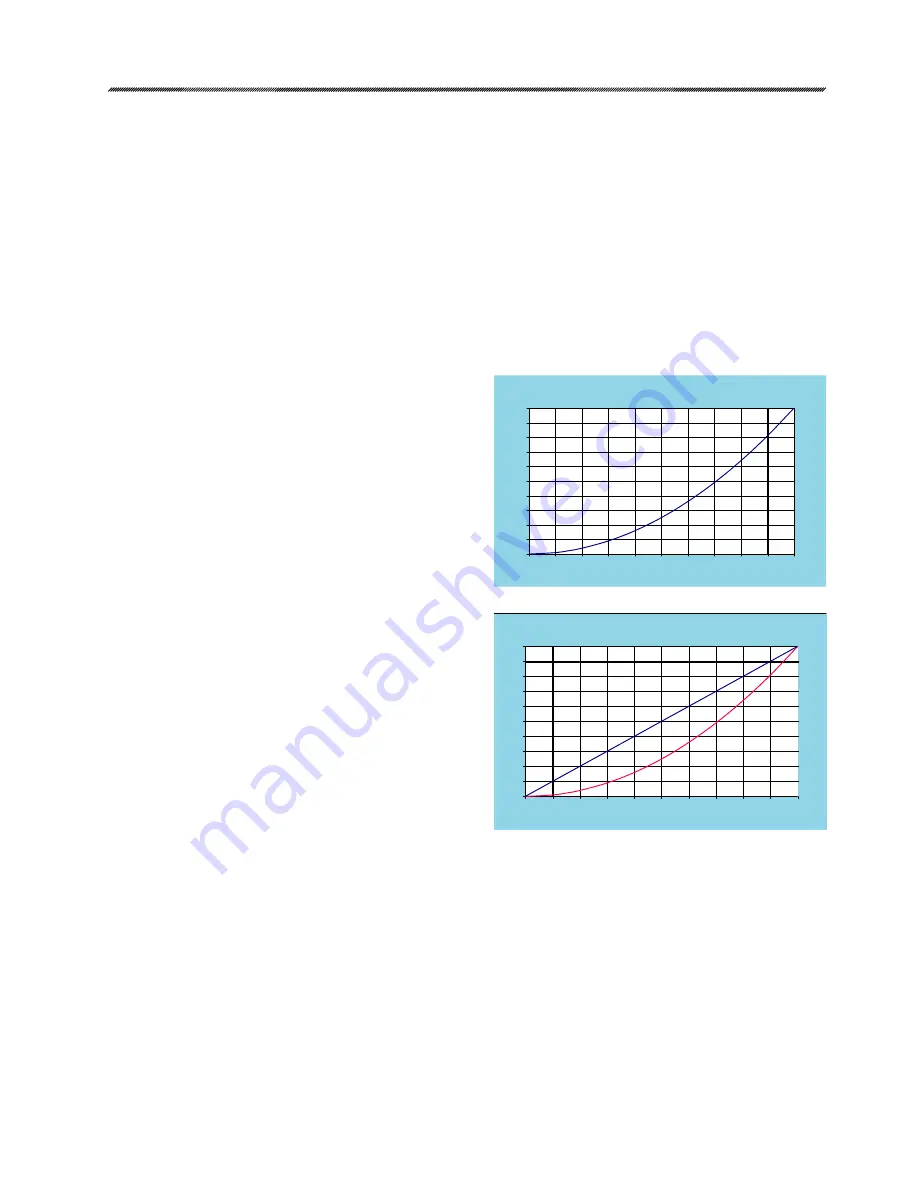
FEEDBACK CURVE EXAMPLE - INVERSE DEMAND
INV
ERS
E D
EM
AN
D F
EED
BAC
K
Applied Demand (% Span)
% Span
0
0
10
20
30
40
50
60
70
80
90
100
10
20
30
40
50
60
70
80
90
100
LINE
AR F
EED
BAC
K C
UR
VE
ACT
UAL
PO
SIT
ION
CU
RV
E
FEEDBACK CURVE EXAMPLE - LINEAR
4
8
12
16
20
Applied Demand (milliamps)
Actual
Position
(milliamps)
4
8
12
16
20
0
10
20
30
40
50
60
70
80
90
100
Actual
Position
(%
Span)
POSITION FEEDBACK SIGNAL
DCM-2 control electronics provide a 4-20 mA
analog output signal that represents the actuator
output shaft position. The DCM-2 monitors an
internal position voltage from the CPS-4, controls
the actuator position, and sources a 4-20 mA
signal to terminals 16(-) and 17 (+). The feedback
will correspond with the 0% and 100% output
shaft positions, as determined by the position
calibration (page 29). There is no need for a
separate feedback calibration.
The user has the option of enabling or disabling
the position feedback signal. The factory default
configuration will have the feedback enabled.
When the feedback is enabled, but not in use
(i.e., not wired to a load) the STAT and FB OPEN
LEDs will illuminate. This status alarm is helpful in
alerting the user to open feedback wiring, but can
be a nuisance when the feedback is purposely
disconnected or unused. Disabling the feedback
signal turns off the output and eliminates the status
alarm. If HART or serial communications are not
immediately available to disable the feedback
signal, you can apply up to an 800 ohm load
resistor across the feedback terminals 16 (-) and
17 (+) to simulate a feedback loop and eliminate
the alarm.
If desired, the milliamp position feedback
values for 0% and 100% positions can be
configured different than the respective standard
factory calibration of 4 mA and 20 mA. The
0% position can be configured between 3-16
mA, while the 100% position can be configured
between 7-21 mA. The 100% milliamp value must
exceed the 0% value by at least 4 mA for proper
configuration. Note: The position feedback and
Demand signals must move in the same direction.
For example, if a damper is driven to its closed
position with a 0% Demand signal (4 mA), the
corresponding feedback signal will be the lowest
milliamp vlaue of the configured position feedback
range (4 mA). It is not possible to reverse the
feedback signal configuration with respect to the
Demand.
A relationship exists between the position
feedback signal and the output shaft position. The
factory calibrated relationship between them is
linear. For example, when the output shaft is at
50%, the position feedback signal will show 50%
(12 mA for a 4-20 mA configuration). Another
relationship is available called “inverted Demand”.
It may be preferable to configure the feedback
for an “inverted Demand” relationship when the
actuator is configured with a non-linear Demand.
The following example ass
umes a 4-20mA
Demand and position configuration.
If the Demand
is set to a square characterization, then a 12mA
Demand corresponds to 25% position. If the
position feedback is set to linear, then feedback at
25% would be 8mA. For some control systems,
having the Demand at 12mA and the feedback at
8mA may cause a deviation alarm. The feedback
characterization can be set to the inverse Demand
curve so the Demand and feedback match when
the actuator is balanced. In this example, with
feedback set to Inverse Demand and the output
shaft position at 25%, the feedback signal would
be 12mA.


