


7-1
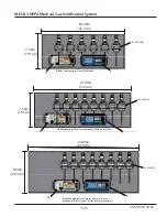
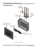
MEGA3 NFPA Medical Gas Notification System
4107 9016 59.03
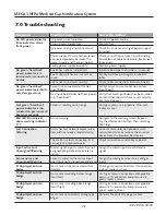
7.0 Troubleshooting
Symptom
Possible Cause
Corrective Action
No LED power indicator
illuminated on alarm
front panel
AC power is not turned on
Check AC power source.
Blown power supply fuse
Replace fuse.
AC power wiring is not connected
Check AC entrance wiring at power supply
terminals.
Power supply DC wire harness is not
connected properly between the
power supply and the main board
Check connections on each end including
orientation of cable connectors. Reconnect
if necessary.
Faulty power supply assembly
Replace power supply
No green “heartbeat”
power indicator is il-
luminated on connected
boards
Board has not been initialized
Initialize board per instructions in manual.
Board dip switches are not set cor-
rectly.
Set dip switches per diagram on board
label.
Cable not connected correctly
Check cable connections between boards.
No green “heartbeat”
power indicator is illumi-
nated on gas sensor
Sensor not connected to the Gas
Input Board.
Verify correct sensor connection to Gas
Input Board.
Gas Input Board does not have power
(no “heartbeat”)
Verify that Gas Input Board has been initial-
ized and that dip switches are set correctly.
See item 2 above.
Fast green "heartbeat"
power indicator is illu-
minated on gas sensor (2
beats per second)
Sensor is reading out of range
Verify gas pressure in pipeline. If normal,
replace sensor.
Red LED illuminated
above warning indicator
( ! ).
Active warning
Navigate to the warning screen by press-
ing the Information button, then selecting
Warnings.
Lost Connection
Warning
Alarm has lost network communica-
tion with manually enrolled device
Correct communication problem with
networked device or remove the enrolled
device from the Enrolled Devices list.
The alarm has lost connection to a
connected/ initialized board.
Check connections and cable to board.
Input active and
Unassigned Warning
Master signal input is wired, but not
assigned/programmed to an alarm
signal
Assign the wired input to a valid alarm
signal.
Sensor active and
Unassigned Warning
Sensor is wired to the sensor input
board, but not assigned/programmed
Assign the wired gas sensor to a valid gas
input.
F1 displayed on Area
badge
Gas sensor is not connected or has
shorted.
Check gas sensor connection. If connection
is good, replace sensor.
F2 displayed on Area
badge
Gas sensor is reading below range
(fault low).
Verify gas sensor connections and pipeline
pressure. If connection and pressure are
good, replace sensor.
F3 displayed on Area
Badge
Gas sensor is reading above range
(fault high).
Verify gas sensor connections and pipeline
pressure. If connection and pressure are
good, replace sensor.
F4 displayed on Area
Badge
Gas sensor connected is wrong type
of gas.
Connect the correct type gas sensor.


