


2-10
MEGA3 NFPA Medical Gas Notification System
4107 9016 59.03
NOTE
:
Do not ground shield drain wire at sensor.
NOTE
:
If gas sensor wires are landed on the terminal
blocks in the same order as defined by the
model number of the alarm panel, then initial
setup will be easier and gas sensor channels
will not need to be reconfigured.” Example
T3-A10-OAV means “O” Oxygen is defaulted to
D01, “A” Medical Air is defaulted to D02, etc.
See section 1.6.
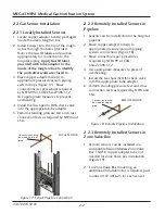
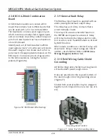
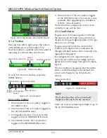
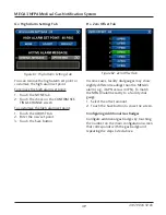
Figure 31: Remote Sensor Module Connection
Figure 30: Local Sensor Mounting
2.4.2 Locally Installed Sensors
1. Remove sensor module from shipping
carton.
2. Connect sensor with DISS fitting to the
appropriate DISS check at the top of the
rough-in box. Verify Gas ID labels match
between the sensor and piping to ensure
no cross connections occur. Repeat this
process for all sensors within alarm panel.
3. Connect wires into input terminals of B60
board (See section 2.4.2).
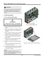
2.4.3 Remotely Installed Sensors in
Pipeline
1. Remove sensor from shipping carton.
2. Connect sensor with DISS fitting to the
appropriate DISS Check on the hospital
pipeline or BeaconMedæs Zone Valve box.
Verify Gas ID labels match between the
sensor and piping to ensure no cross con-
nections occur.
3. Wire nut pigtail to field installed wiring.
Note polarity of wiring and corresponding
field wiring color or number for later (See
section 2.3.5).


