


2-2
MEGA3 NFPA Medical Gas Notification System
4107 9016 59.03
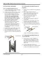
2.2 Gas Sensor Installation
2.2.1 Locally Installed Sensors
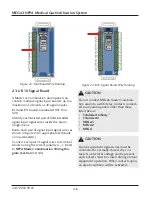
1. Locate copper adapter tube(s) packaged
inside the alarm rough-in box.
2. Install tube(s) into the top of the rough-
in box through the holes provided.
Notice the Gas ID labels and position
appropriately for connection to the
hospital piping.
Apply Gas ID label
provided with tube adapter to the
inside of the rough-in box to identify
the ports after walls are closed in.
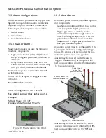
3. Braze copper adapter tube(s) to
appropriate pressure/vacuum piping
system drops (Figure 17). Braze
connections per procedures required
by NFPA 99 or CAN/CSA-Z7396.1-12.
Use appropriate measures to prevent
overheating.
4. Install the Gas Specific DISS check valve
into the appropriate tube adapter.
5. Perform standing pressure test and cross
connection tests as required by NFPA and
CSA.
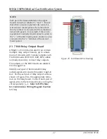
2.2.2 Remotely Installed Sensors in
Pipeline
1. Sensors can be installed onto the hospital
pipeline.
2. Braze copper adapter tube(s) to
appropriate pressure/vacuum piping
system connections (Figure 18).
3. Braze connections per procedures
required by NFPA 99 or CAN/
CSA-Z7396.1-12
4. Use appropriate measures to prevent
overheating.
5. Install the Gas Specific DISS check valve
into the appropriate tube adapter.
6. Perform standing pressure test and cross
connection tests as required by NFPA and
CSA.
2.2.3 Remotely Installed Sensors in
Zone Valve Box
1. Remote sensors can be installed in a
compatible BeaconMedæs Zone Valve
Box. (NOTE: copper adapter tube not
needed for Zone Valve box installation
(Figure 19).
2. For Zone Valve Box mounting, an
additional Installation Kit is required, part
number 4107 4016 25 for each sensor.
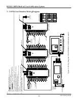
Figure
17: Sensor Pipeline Connection
Connection should
be made on top of
pipe
LOCAL SENSOR
REMOTE SENSOR
Connection should
be made on top of
pipe
Figure
18: Remote Pipeline Installation


