


5-3
MEGA3 NFPA Medical Gas Notification System
4107 9016 59.03
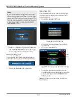
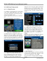
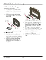
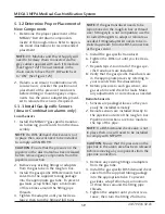
4. The last module in the chain needs to
have the #1 DIP switch set to “ON” (Fig-
ure 123). Refer to the module ID label.
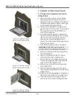
2. Mount the I/O Modules inside the rough-
in box using the supplied hardware.
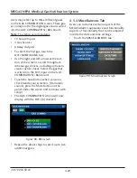
3. Connect the grey cable(s) provided; from
the power supply to the white sockets on
the I/O modules in a daisy chain manner
(Figure 122).
Figure 122: Daisy Chain of Power Supply
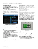
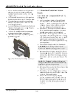
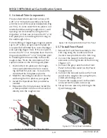
5.1.3 Install New Components
1. Determine the best placement of the re-
maining I/O modules inside of the rough-
in box.
NOTE:
I/O Modules and Power Supply will
need to be daisy chain connected via the
grey cables supplied with each I/O module.
Figure 123: DIP Switch Setting
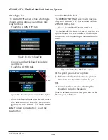
5. Connect all input signal / output signal /
gas sensor wiring to their respective mod-
ules. Refer to the wiring diagram on the
Quick Setup Guide for instructions.
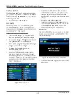
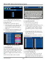
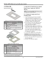
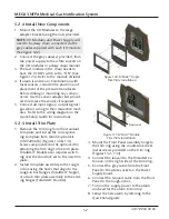
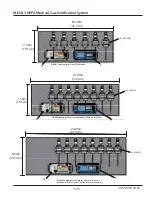
5.1.4 Install Trim Plate
MEGA Master / Area 4 Gas
a. Install trim plate assembly to rough-in
box using the provided screws and/or
drywall anchors. Slots in the trim plate
will align with existing holes in the
rough-in box flanges (Figure 124).
NOTE:
Trim ring portion can be removed
from the trim plate if the surrounding wall
area is in good condition. Mounting of the
trim ring only to the rough-in box will result
in a cleaner retrofit installation.
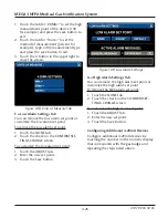
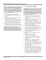
TA2/MEGA2 Area 8 Gas
a. Remove the trim ring from the standard
trim plate and install the wide 27” wide
x 16” tall trim plate from retrofit option
kit (4107220615). Screws are provided
in the option kit for attaching the trim
ring to the trim plate (Figure 124).
b. Install trim plate assembly to rough-in
box using the provided screws and/or
drywall anchors. Slots in the trim plate
will align with existing holes in the
rough-in box flanges.
Figure 124: Retrofit Area Trim Panel
Trim Plate
Trim Ring


