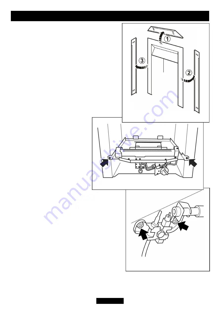
17.2 To remove the fascia.
1.
Remove the bottom front cover and the fire
front casting.
2.
The fascia is made up of three pieces. These
pieces are held in place by magnets. Remove the
top fascia piece by pulling forward. Place
carefully aside (See figure 35).
3.
Remove the side fascia pieces by pulling
forward. Place carefully aside
(See figure 35).
4.
Refit in the reverse order. Make sure that the
top corners of the fascia have no gaps.
17.3 To remove the burner unit.
1.
Remove the bottom front and
fire front castings and the fascia
(See section 17.2).
2.
Remove the loose ceramic fuel
effect pieces, the front ceramic fuel
effect and the base ceramic fuel
effect.
3.
Support the inlet ‘T’ connector
to avoid straining the pipework and
disconnect the appliance from the
‘T’ connector.
4.
Detach the burner unit from the hotbox by
removing two screws (See figure 36).
5.
Replace in the reverse order.
17.4 To remove the pilot unit.
1.
Remove the burner unit (See section 17.3).
2.
Detach the pilot pipe from the pilot unit.
3.
Detach the thermocouple from the gas valve
4.
Detach the electrode lead from the underside of
the electrode tab.
6.
Remove the two screws securing the pilot unit
(See figure 37).
7.
Refit in the reverse order.
Note:
1.
The pilot unit is an atmosphere sensing device. It must be replaced as
a whole assembly. Its individual components are not separately replaceable.
Page 32
INSTALLER GUIDE
Figure 37. Pilot unit removal
Figure 36. Burner attachment points
Figure 35. Removing the fascia.


