9310200990 Rev G
BE1-79A Installation and Configuration
5-1
SECTION 5
•
INSTALLATION AND
CONFIGURATION
GENERAL
BE1-79A Reclosing Relays are delivered in sturdy cartons to prevent shipping damage. Upon receipt of a
relay, check the model number against the requisition and packing list for agreement. Inspect for damage
and, if there is evidence of such, file a claim with the carrier and notify the Basler Electric regional sales
office, your sales representative, or the Technical Sales Support department of Basler Electric.
If the relay is not installed immediately, store it in the original shipping carton in a moisture- and dust-free
environment.
MOUNTING
Because the BE1-79A is of solid-state design, it does not have to be mounted vertically. Any convenient
mounting angle may be chosen. The BE1-79A is available in an S2 cradle or an S1 cradle with case. The
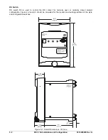
S2 cradle is intended for installation in an existing S2 case. Overall dimensions for the S1 case are shown
in Figure 5-1. S1 case cutout dimensions are shown in Figure 5-2.
CONNECTIONS
Incorrect wiring may result in damage to the relay. Be sure to use the correct input power for the power
supply and the correct input voltage for the contact inputs. Connections should be made with a minimum
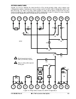
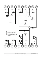
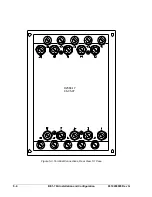
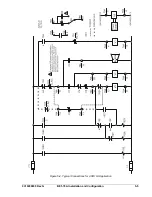
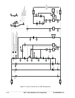
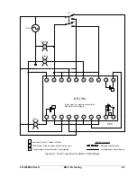
wire size of 14 AWG. Figure 5-3 illustrates the terminal connections of the S1 case. Figure 5-4 provides a
typical connection diagram for an application using an ACR11A style relay. Figure 5-5 shows typical
connections for an application using an ACR11B style relay.
APPLICATION
The intended function of the BE1-79A Reclosing Relay is to duplicate an ACR11 recloser with only minor
variations. To ensure that your BE1-79A relay functions properly, you should consider the adjustments
and settings described in the following paragraphs.
Style Configuration Switches
Switches S1, S2, and S3 must be set properly for your application. All three switches should be placed in
the A (up) position for ACR11A operation. All three switches should be placed in the B (down) position for
ACR11B, ACR11C, ACR11E, and ACR11F operation.
Instantaneous Reclose Jumper Switch
Use the following guidelines when setting Instantaneous Reclose Jumper Switch S4.
•
For ACR11a operation, switch S4 should be placed in the EXT (down) position.
•
An ACR relay has a red jumper from terminals 13 to 17 for an instantaneous first reclosure
(SP-79A1 0.0,X.X) is duplicated by placing BE1-79A switch S4 in the INT (up) position.
•
A delayed first reclosure is achieved when S4 is placed in the EXT (down) position and the external
jumper is removed from terminals 13 and 17.
•
If an external jumper is left in place at terminals 13 and 17 for an instantaneous first reclosure, S4
should be placed in the EXT (down) position.
•
Neither an internal nor an external jumper is required at terminals 12 and 13 for a delayed first
reclosure. Switch S4 should be placed in the EXT (down) position for delayed reclosures.
NOTE
Be sure that the BE1-79A is hard-wired to earth ground with no smaller than 12
AWG copper wire attached to the ground terminal on the rear of the unit case.
When the relay is configured in a system with other devices, a separate lead to
the ground bus is recommended for each device.
Содержание BE1-79A
Страница 1: ...INSTRUCTION MANUAL FOR RECLOSING RELAY BE1 79A Publication 9310200990 Revision G 02 08...
Страница 2: ......
Страница 8: ...vi BE1 79A Introduction 9310200990 Rev G This page intentionally left blank...
Страница 10: ...ii BE1 79A General Information 9310200990 Rev G This page intentionally left blank...
Страница 16: ...ii BE1 79A Controls and Indicators 9310200990 Rev G This page intentionally left blank...
Страница 20: ...2 4 BE1 79A Controls and Indicators 9310200990 Rev G This page intentionally left blank...
Страница 22: ...ii BE1 79A Functional Description 9310200990 Rev G This page intentionally left blank...
Страница 34: ...ii BE1 79A Communication Commands 9310200990 Rev G This page intentionally left blank...
Страница 40: ...ii BE1 79A Installation and Configuration 9310200990 Rev G This page intentionally left blank...
Страница 43: ...9310200990 Rev G BE1 79A Installation and Configuration 5 3 Figure 5 2 Panel Cutout Dimensions S1 Case...
Страница 52: ...ii BE1 79A Testing 9310200990 Rev G This page intentionally left blank...
Страница 58: ...6 6 BE1 79A Testing 9310200990 Rev G This page intentionally left blank...
Страница 60: ...ii BE1 79A RS Contact Application 9310200990 Rev G This page intentionally left blank...
Страница 66: ...ii BE1 79A Terminal Communication 9310200990 Rev G This page intentionally left blank...

