


6-2
Maintenance
BE1-67
Test plugs consist of a black and red phenolic molding with twenty electrically separated contact fingers
connected to ten coaxial binding posts. The ten fingers on the black side are connected to the inner binding
posts (black thumb nuts) and tap into the relay internal circuitry. The ten fingers on the red side of the test plug
are connected to the outer binding posts (red thumb nuts) and to the relay case terminals.
When testing circuits connected to the bottom set of case terminals, the test plug is inserted with the numbers
1 through 10 facing up. When using the test plug in the upper part of the relay, the numbers 11 through 20
are face up. Because of the test plug construction, it is impossible to insert it with the wrong orientation.
Содержание BE1-67
Страница 22: ...1 16 General Information BE1 67 Figure 1 12 Timing Type B1 Short Inverse Drawing Number 99 0932...
Страница 23: ...BE1 67 General Information 1 17 Figure 1 13 Timing Type B2 Long Inverse Drawing Number 99 0931...
Страница 24: ...1 18 General Information BE1 67 Figure 1 14 Timing Type B3 Definite Time Drawing Number 99 0933...
Страница 25: ...BE1 67 General Information 1 19 Figure 1 15 Timing Type B4 Moderate Inverse Drawing Number 99 0930...
Страница 26: ...1 20 General Information BE1 67 Figure 1 16 Timing Type B5 Inverse Drawing Number 99 0929...
Страница 27: ...BE1 67 General Information 1 21 Figure 1 17 Timing Type B6 Very Inverse Drawing Number 99 0928...
Страница 28: ...1 22 General Information BE1 67 Figure 1 18 Timing Type B7 Extremely Inverse Drawing Number 99 0927...
Страница 29: ...BE1 67 General Information 1 23 Figure 1 19 Timing Type E2 BS 142 Long Inverse Drawing Number 99 1093...
Страница 30: ...1 24 General Information BE1 67 Figure 1 20 Timing Type E4 BS 132 Inverse Drawing Number 99 1094...
Страница 31: ...BE1 67 General Information 1 25 Figure 1 21 Timing Type E5 BS 142 Inverse Drawing Number 99 1095...
Страница 32: ...1 26 General Information BE1 67 Figure 1 22 Timing Type E6 BS 142 Very Inverse Drawing Number 99 1096...
Страница 33: ...BE1 67 General Information 1 27 Figure 1 23 Timing Type E7 BS 142 Extremely Inverse Drawing Number 99 1097...
Страница 35: ...2 2 Human Machine Interface BE1 67 Figure 2 1 BE1 67 Three Phase Relay With Characteristic Angle Control Knob...
Страница 39: ...2 6 Human Machine Interface BE1 67 Figure 2 3 Location of Assemblies Controls and Indicators...
Страница 47: ...4 2 Installation BE1 67 Figure 4 1 Outline Dimensions Front View...
Страница 48: ...BE1 67 Installation 4 3 Figure 4 2 Outline Dimensions Rear View...
Страница 49: ...4 4 Installation BE1 67 Figure 4 3 Outline Dimensions Side View Semi Flush Mounting...
Страница 50: ...BE1 67 Installation 4 5 Figure 4 4 Outline Dimensions Side View Projection Mounting...
Страница 51: ...4 6 Installation BE1 67 Figure 4 5 Panel Drilling Diagram Semi Flush Mounting...
Страница 52: ...BE1 67 Installation 4 7 Figure 4 6 Panel Drilling Diagram Projection Mounting...
Страница 54: ...BE1 67 Installation 4 9 Figure 4 8 Single Phase AC Connections...
Страница 55: ...4 10 Installation BE1 67 Figure 4 9 Three Phase AC Connections...
Страница 56: ...BE1 67 Installation 4 11 Figure 4 10 BE1 67 Single Phase Internal Connection Diagram...
Страница 57: ...4 12 Installation BE1 67 Figure 4 11 BE1 67 Three Phase Internal Connection Diagram...
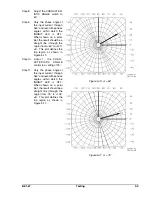
Страница 62: ...BE1 67 Testing 5 5 Figure 5 3 Blank Polar Graph Form Figure 5 4 Blank Polar Graph Form...


