


BE1-67
General Information
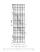
1-13
(a) Continuously adjustable over the range of 0 to 90°
(b ) Switch selectable settings of 30°, 45°, 60° and 75°
Repeatability
Repeatability is ±5° from the setting at nominal system frequency.
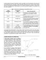
Limited Range of Operation (Optional)
The front panel control is continuously adjustable over the range of +5°to +90°. The total individual angle of
the Limited Range of Operation will accordingly vary from 10° to 180°.
Frequency Range
The unit is designed to operate on power systems with a nominal frequency of either 50 or 60 hertz. The unit
has been type-tested for proper operation over the frequency range of 45 to 55 hertz for 50 hertz systems and
55 to 65 hertz for 60 hertz systems.
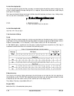
Power Supply
Power for the internal circuitry may be derived from a variety of ac or dc external power sources as indicated
in Table 1-5.
Table 1-5. Power Supply Specifications
Type
Nominal
Input
Voltage
Input
Voltage
Range
Burden
at
Nominal
K
48 Vdc
24 to 60 Vdc
7.0 W
J
125 Vdc
120 Vac
62 to 150 Vdc
90 to 132 Vac
10.0 W
20.0 VA
*
L
24 Vdc
12 to 32 Vdc
7.0 W
†
Y
48 Vdc
125 Vdc
24 to 60 Vdc
62 to 150 Vdc
7.0 W
7.5 W
Z
250 Vdc
230 Vac
140 to 280 Vdc
190 to 270 Vac
8.5 W
22.0 VA
NOTES: All references are at 50/60 Hz.
*
Type L Power Supply may require 14 Vdc to begin operation. Once operating, the
voltage may be reduced to 12 Vdc.
†
Type Y Power Supply is field-selectable for 48 or 125 Vdc. Selection must be implemented
at time of installation. This power supply option is factory set for 125 Vdc.
Target Indicators
Function targets may be specified as either internally operated or current operated by a minimum of 0.2
amperes through the output trip circuit. When current operated, the output circuit must be limited to 30
amperes for 0.2 seconds, 7 amperes for 2 minutes and 3 amperes continuously.
Single-Phase Units
When specified by the style number, either an internally operated or a current operated target will be supplied
for each of the tripping outputs included within the relay (i.e., the time and instantaneous overcurrent
functions).
Содержание BE1-67
Страница 22: ...1 16 General Information BE1 67 Figure 1 12 Timing Type B1 Short Inverse Drawing Number 99 0932...
Страница 23: ...BE1 67 General Information 1 17 Figure 1 13 Timing Type B2 Long Inverse Drawing Number 99 0931...
Страница 24: ...1 18 General Information BE1 67 Figure 1 14 Timing Type B3 Definite Time Drawing Number 99 0933...
Страница 25: ...BE1 67 General Information 1 19 Figure 1 15 Timing Type B4 Moderate Inverse Drawing Number 99 0930...
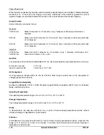
Страница 26: ...1 20 General Information BE1 67 Figure 1 16 Timing Type B5 Inverse Drawing Number 99 0929...
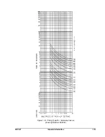
Страница 27: ...BE1 67 General Information 1 21 Figure 1 17 Timing Type B6 Very Inverse Drawing Number 99 0928...
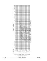
Страница 28: ...1 22 General Information BE1 67 Figure 1 18 Timing Type B7 Extremely Inverse Drawing Number 99 0927...
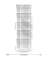
Страница 29: ...BE1 67 General Information 1 23 Figure 1 19 Timing Type E2 BS 142 Long Inverse Drawing Number 99 1093...
Страница 30: ...1 24 General Information BE1 67 Figure 1 20 Timing Type E4 BS 132 Inverse Drawing Number 99 1094...
Страница 31: ...BE1 67 General Information 1 25 Figure 1 21 Timing Type E5 BS 142 Inverse Drawing Number 99 1095...
Страница 32: ...1 26 General Information BE1 67 Figure 1 22 Timing Type E6 BS 142 Very Inverse Drawing Number 99 1096...
Страница 33: ...BE1 67 General Information 1 27 Figure 1 23 Timing Type E7 BS 142 Extremely Inverse Drawing Number 99 1097...
Страница 35: ...2 2 Human Machine Interface BE1 67 Figure 2 1 BE1 67 Three Phase Relay With Characteristic Angle Control Knob...
Страница 39: ...2 6 Human Machine Interface BE1 67 Figure 2 3 Location of Assemblies Controls and Indicators...
Страница 47: ...4 2 Installation BE1 67 Figure 4 1 Outline Dimensions Front View...
Страница 48: ...BE1 67 Installation 4 3 Figure 4 2 Outline Dimensions Rear View...
Страница 49: ...4 4 Installation BE1 67 Figure 4 3 Outline Dimensions Side View Semi Flush Mounting...
Страница 50: ...BE1 67 Installation 4 5 Figure 4 4 Outline Dimensions Side View Projection Mounting...
Страница 51: ...4 6 Installation BE1 67 Figure 4 5 Panel Drilling Diagram Semi Flush Mounting...
Страница 52: ...BE1 67 Installation 4 7 Figure 4 6 Panel Drilling Diagram Projection Mounting...
Страница 54: ...BE1 67 Installation 4 9 Figure 4 8 Single Phase AC Connections...
Страница 55: ...4 10 Installation BE1 67 Figure 4 9 Three Phase AC Connections...
Страница 56: ...BE1 67 Installation 4 11 Figure 4 10 BE1 67 Single Phase Internal Connection Diagram...
Страница 57: ...4 12 Installation BE1 67 Figure 4 11 BE1 67 Three Phase Internal Connection Diagram...
Страница 62: ...BE1 67 Testing 5 5 Figure 5 3 Blank Polar Graph Form Figure 5 4 Blank Polar Graph Form...


