


3-4
Functional Description
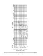
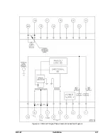
BE1-67
Figure 3-3.
Limited Region of Operation
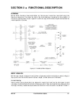
INDICATORS
Depending on the options provided, up to five different indicators are visible on the front panel. They are:
!
INHIBIT LED's
!
TIMING LED's
!
POWER LED
!
FUNCTION targets
!
ELEMENT targets
INHIBIT LED's
When the phase relationship between the current(s) and voltage(s) do not meet the criteria of the directional
element, an inhibit signal is output. This signal lights the appropriate PHASE INHIBIT LED on the relay front
panel and prevents the operation of the time overcurrent function in the relay. It also inhibits the directional
instantaneous overcurrent element (optional) operation.
TIMING LED's
Red LED's that light when the pickup setting of a TIME overcurrent element of the relay is exceeded. One LED
is included for each phase monitored by the relay. LED's may be used to determine the actual pickup setting
of the relay during testing.
POWER LED's
A red LED lights when the relay power supply is functioning. This provides a front panel indication of the relay
status.
FUNCTION Targets
These magnetically latched indicators change from black to orange when the corresponding TIME overcurrent
or INST (instantaneous) overcurrent function causes the trip output relays to be energized or current to flow
through the output contacts.
ELEMENT Targets
Magnetically latched indicators that change from black to orange when tripping occurs to show the phase(s)
that caused the trip. Not present on single-phase relays.
POWER SUPPLY
Basler Electric enhanced the power supply design for unit case relays. This new design created three, wide
range power supplies that replace the four previous power supplies. Style number identifiers for these power
supplies have not been changed so that customers may order the same style numbers that they ordered
Содержание BE1-67
Страница 22: ...1 16 General Information BE1 67 Figure 1 12 Timing Type B1 Short Inverse Drawing Number 99 0932...
Страница 23: ...BE1 67 General Information 1 17 Figure 1 13 Timing Type B2 Long Inverse Drawing Number 99 0931...
Страница 24: ...1 18 General Information BE1 67 Figure 1 14 Timing Type B3 Definite Time Drawing Number 99 0933...
Страница 25: ...BE1 67 General Information 1 19 Figure 1 15 Timing Type B4 Moderate Inverse Drawing Number 99 0930...
Страница 26: ...1 20 General Information BE1 67 Figure 1 16 Timing Type B5 Inverse Drawing Number 99 0929...
Страница 27: ...BE1 67 General Information 1 21 Figure 1 17 Timing Type B6 Very Inverse Drawing Number 99 0928...
Страница 28: ...1 22 General Information BE1 67 Figure 1 18 Timing Type B7 Extremely Inverse Drawing Number 99 0927...
Страница 29: ...BE1 67 General Information 1 23 Figure 1 19 Timing Type E2 BS 142 Long Inverse Drawing Number 99 1093...
Страница 30: ...1 24 General Information BE1 67 Figure 1 20 Timing Type E4 BS 132 Inverse Drawing Number 99 1094...
Страница 31: ...BE1 67 General Information 1 25 Figure 1 21 Timing Type E5 BS 142 Inverse Drawing Number 99 1095...
Страница 32: ...1 26 General Information BE1 67 Figure 1 22 Timing Type E6 BS 142 Very Inverse Drawing Number 99 1096...
Страница 33: ...BE1 67 General Information 1 27 Figure 1 23 Timing Type E7 BS 142 Extremely Inverse Drawing Number 99 1097...
Страница 35: ...2 2 Human Machine Interface BE1 67 Figure 2 1 BE1 67 Three Phase Relay With Characteristic Angle Control Knob...
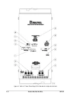
Страница 39: ...2 6 Human Machine Interface BE1 67 Figure 2 3 Location of Assemblies Controls and Indicators...
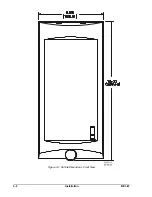
Страница 47: ...4 2 Installation BE1 67 Figure 4 1 Outline Dimensions Front View...
Страница 48: ...BE1 67 Installation 4 3 Figure 4 2 Outline Dimensions Rear View...
Страница 49: ...4 4 Installation BE1 67 Figure 4 3 Outline Dimensions Side View Semi Flush Mounting...
Страница 50: ...BE1 67 Installation 4 5 Figure 4 4 Outline Dimensions Side View Projection Mounting...
Страница 51: ...4 6 Installation BE1 67 Figure 4 5 Panel Drilling Diagram Semi Flush Mounting...
Страница 52: ...BE1 67 Installation 4 7 Figure 4 6 Panel Drilling Diagram Projection Mounting...
Страница 54: ...BE1 67 Installation 4 9 Figure 4 8 Single Phase AC Connections...
Страница 55: ...4 10 Installation BE1 67 Figure 4 9 Three Phase AC Connections...
Страница 56: ...BE1 67 Installation 4 11 Figure 4 10 BE1 67 Single Phase Internal Connection Diagram...
Страница 57: ...4 12 Installation BE1 67 Figure 4 11 BE1 67 Three Phase Internal Connection Diagram...
Страница 62: ...BE1 67 Testing 5 5 Figure 5 3 Blank Polar Graph Form Figure 5 4 Blank Polar Graph Form...


