


BE1-67
Maintenance
6-1
CAUTION
Substitution of printed circuit boards or individual components does not necessarily mean
the relay will operate properly. Always test the relay before placing it in operation.
SECTION 6
MAINTENANCE
GENERAL
The BE1-67, Phase Directional Overcurrent Relay, requires no preventive maintenance other than periodic
tests. (Refer to Section 5 for test procedures.) If factory repair is desired, contact the Customer Service
Department of the Power Systems Group, Basler Electric, for a return authorization number prior to shipping.
IN-HOUSE REPAIR
In-house replacement of individual components may be difficult and should not be attempted unless
appropriate equipment and qualified personnel are available.
If in-house repair is to be attempted, component values may be obtained from the schematics or the parts list
of the Service Manual. Replacement parts may be purchased locally. The quality of replacement parts must
be at least equal to that of the original components.
Where special components are involved, Basler Electric part numbers may be obtained from the number
stamped on the component or assembly, the schematic or parts list. These parts may be ordered directly from
Basler Electric. When complete boards or assemblies are needed, the following information is required.
1. Relay model and style number
2. Relay serial number
3. Board or assembly
a) Part number
b) Serial number
c) Revision letter
4. The name of the board or assembly
STORAGE
This protective relay contains aluminum electrolytic capacitors which generally have a life expectancy in
excess of 10 years at storage temperatures less than 40 degrees C. Typically, the life expectancy of the
capacitor is cut in half for every 10 degrees C rise in temperature. Storage life can be extended if, at one-year
intervals, power is applied to the relay for a period of thirty minutes.
TEST PLUG
Test plugs (Basler p/n 10095) provide a quick, easy method of testing relays without removing them from the
case. Test plugs are simply substituted for the connection plugs. This provides access to the external stud
connections as well as to the internal circuitry.
Содержание BE1-67
Страница 22: ...1 16 General Information BE1 67 Figure 1 12 Timing Type B1 Short Inverse Drawing Number 99 0932...
Страница 23: ...BE1 67 General Information 1 17 Figure 1 13 Timing Type B2 Long Inverse Drawing Number 99 0931...
Страница 24: ...1 18 General Information BE1 67 Figure 1 14 Timing Type B3 Definite Time Drawing Number 99 0933...
Страница 25: ...BE1 67 General Information 1 19 Figure 1 15 Timing Type B4 Moderate Inverse Drawing Number 99 0930...
Страница 26: ...1 20 General Information BE1 67 Figure 1 16 Timing Type B5 Inverse Drawing Number 99 0929...
Страница 27: ...BE1 67 General Information 1 21 Figure 1 17 Timing Type B6 Very Inverse Drawing Number 99 0928...
Страница 28: ...1 22 General Information BE1 67 Figure 1 18 Timing Type B7 Extremely Inverse Drawing Number 99 0927...
Страница 29: ...BE1 67 General Information 1 23 Figure 1 19 Timing Type E2 BS 142 Long Inverse Drawing Number 99 1093...
Страница 30: ...1 24 General Information BE1 67 Figure 1 20 Timing Type E4 BS 132 Inverse Drawing Number 99 1094...
Страница 31: ...BE1 67 General Information 1 25 Figure 1 21 Timing Type E5 BS 142 Inverse Drawing Number 99 1095...
Страница 32: ...1 26 General Information BE1 67 Figure 1 22 Timing Type E6 BS 142 Very Inverse Drawing Number 99 1096...
Страница 33: ...BE1 67 General Information 1 27 Figure 1 23 Timing Type E7 BS 142 Extremely Inverse Drawing Number 99 1097...
Страница 35: ...2 2 Human Machine Interface BE1 67 Figure 2 1 BE1 67 Three Phase Relay With Characteristic Angle Control Knob...
Страница 39: ...2 6 Human Machine Interface BE1 67 Figure 2 3 Location of Assemblies Controls and Indicators...
Страница 47: ...4 2 Installation BE1 67 Figure 4 1 Outline Dimensions Front View...
Страница 48: ...BE1 67 Installation 4 3 Figure 4 2 Outline Dimensions Rear View...
Страница 49: ...4 4 Installation BE1 67 Figure 4 3 Outline Dimensions Side View Semi Flush Mounting...
Страница 50: ...BE1 67 Installation 4 5 Figure 4 4 Outline Dimensions Side View Projection Mounting...
Страница 51: ...4 6 Installation BE1 67 Figure 4 5 Panel Drilling Diagram Semi Flush Mounting...
Страница 52: ...BE1 67 Installation 4 7 Figure 4 6 Panel Drilling Diagram Projection Mounting...
Страница 54: ...BE1 67 Installation 4 9 Figure 4 8 Single Phase AC Connections...
Страница 55: ...4 10 Installation BE1 67 Figure 4 9 Three Phase AC Connections...
Страница 56: ...BE1 67 Installation 4 11 Figure 4 10 BE1 67 Single Phase Internal Connection Diagram...
Страница 57: ...4 12 Installation BE1 67 Figure 4 11 BE1 67 Three Phase Internal Connection Diagram...
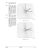
Страница 62: ...BE1 67 Testing 5 5 Figure 5 3 Blank Polar Graph Form Figure 5 4 Blank Polar Graph Form...


