


4-8
Installation
BE1-67
NOTE
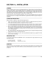
Be sure the relay case is hard-wired to earth ground with no smaller than 12 AWG copper
wire attached to the ground terminal on the rear of the relay case. When the relay is
configured in a system with other protective devices, it is recommended to use a separate
lead to the ground bus from each relay.
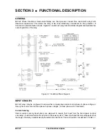
CONNECTIONS
Incorrect wiring may result in damage to the relay. Be sure to check the model and style number of the relay
before connecting and energizing the particular relay.
Except as noted above, connections should be made with minimum wire size of 14 AWG. The following
illustrations provide information on relay connections.
!
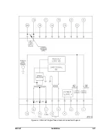
Control circuit connections are shown in Figure 4-7.
!
Typical ac connections for single-phase relays are shown in Figure 4-8.
!
Typical ac connections for three-phase relays are shown in Figure 4-9.
!
Internal connections are shown in Figures 4-10 and 4-11.
Figure 4-7. DC Control Connections
Содержание BE1-67
Страница 22: ...1 16 General Information BE1 67 Figure 1 12 Timing Type B1 Short Inverse Drawing Number 99 0932...
Страница 23: ...BE1 67 General Information 1 17 Figure 1 13 Timing Type B2 Long Inverse Drawing Number 99 0931...
Страница 24: ...1 18 General Information BE1 67 Figure 1 14 Timing Type B3 Definite Time Drawing Number 99 0933...
Страница 25: ...BE1 67 General Information 1 19 Figure 1 15 Timing Type B4 Moderate Inverse Drawing Number 99 0930...
Страница 26: ...1 20 General Information BE1 67 Figure 1 16 Timing Type B5 Inverse Drawing Number 99 0929...
Страница 27: ...BE1 67 General Information 1 21 Figure 1 17 Timing Type B6 Very Inverse Drawing Number 99 0928...
Страница 28: ...1 22 General Information BE1 67 Figure 1 18 Timing Type B7 Extremely Inverse Drawing Number 99 0927...
Страница 29: ...BE1 67 General Information 1 23 Figure 1 19 Timing Type E2 BS 142 Long Inverse Drawing Number 99 1093...
Страница 30: ...1 24 General Information BE1 67 Figure 1 20 Timing Type E4 BS 132 Inverse Drawing Number 99 1094...
Страница 31: ...BE1 67 General Information 1 25 Figure 1 21 Timing Type E5 BS 142 Inverse Drawing Number 99 1095...
Страница 32: ...1 26 General Information BE1 67 Figure 1 22 Timing Type E6 BS 142 Very Inverse Drawing Number 99 1096...
Страница 33: ...BE1 67 General Information 1 27 Figure 1 23 Timing Type E7 BS 142 Extremely Inverse Drawing Number 99 1097...
Страница 35: ...2 2 Human Machine Interface BE1 67 Figure 2 1 BE1 67 Three Phase Relay With Characteristic Angle Control Knob...
Страница 39: ...2 6 Human Machine Interface BE1 67 Figure 2 3 Location of Assemblies Controls and Indicators...
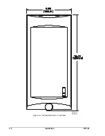
Страница 47: ...4 2 Installation BE1 67 Figure 4 1 Outline Dimensions Front View...
Страница 48: ...BE1 67 Installation 4 3 Figure 4 2 Outline Dimensions Rear View...
Страница 49: ...4 4 Installation BE1 67 Figure 4 3 Outline Dimensions Side View Semi Flush Mounting...
Страница 50: ...BE1 67 Installation 4 5 Figure 4 4 Outline Dimensions Side View Projection Mounting...
Страница 51: ...4 6 Installation BE1 67 Figure 4 5 Panel Drilling Diagram Semi Flush Mounting...
Страница 52: ...BE1 67 Installation 4 7 Figure 4 6 Panel Drilling Diagram Projection Mounting...
Страница 54: ...BE1 67 Installation 4 9 Figure 4 8 Single Phase AC Connections...
Страница 55: ...4 10 Installation BE1 67 Figure 4 9 Three Phase AC Connections...
Страница 56: ...BE1 67 Installation 4 11 Figure 4 10 BE1 67 Single Phase Internal Connection Diagram...
Страница 57: ...4 12 Installation BE1 67 Figure 4 11 BE1 67 Three Phase Internal Connection Diagram...
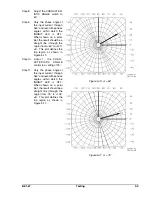
Страница 62: ...BE1 67 Testing 5 5 Figure 5 3 Blank Polar Graph Form Figure 5 4 Blank Polar Graph Form...


