


BE1-67
Human-Machine Interface
2-1
SECTION 2
HUMAN-MACHINE INTERFACE
Table 2-1. BE1-67 Controls and Indicators (refer to Figures 2-1, 2-2 and 2-3)
Locator
Control Or Indicator
Function
A
CHARACTERISTIC
ANGLE
This potentiometer (options 3-1, 3-3, 3-5 or 3-6 ) or 4-position
switch (options 3-2 and 3-4) defines the characteristic angle for
the directional element of the relay.
This potentiometer can adjust the characteristic angle alpha over
the range of 0° to 90° while the 4- position switch can set the
characteristic angle to 30°, 45°, 60° or 75°. When the
potentiometer is knob controlled (as in Figure 2-1), the max CW
position represents the minimum characteristic angle (or 0°).
When the potentiometer is a screwdriver-operated multi-turn
potentiometer (as in Figure 2-2), the max CW position represents
the maximum characteristic angle (or 90°).
B
TAP
Selector
This 10-position rotary switch provides the primary means of
setting the pickup for the overcurrent functions of the relay. When
the TAP CAL control (locator
K
) is in the full clockwise position,
the pickup of the relay is based on the setting of the TAP selector
switch. The setting for the time overcurrent function is the value
defined by the switch position (A to J) and the external
connections (HIGH/LOW tap range).
This control, together with the TAP CAL control, establishes the
pickup level of all phases monitored by the relay. Note that it is
safe to switch the TAP selector without disconnecting the sensing
current.
C
TAP RANGE
Plate
This plate is adjusted to indicate HIGH or LOW, the setting range
corresponding to the connections on the back of the relay.
D
POWER
Indicator
A red LED is lit when the relay power supply is functioning. This
provides a front panel indication of the relay status. An optional
POWER SUPPLY STATUS ALARM contact (Options 3-3 and 3-
4) is available to provide a remote indication of this condition.
E
FUNCTION
Targets
These magnetically latched indicators change from black to
orange when the corresponding TIME overcurrent or INST
(instantaneous) overcurrent function causes the trip output relays
to be energized or current to flow through the output contacts.
F
TARGET RESET
Lever
This lever engages the reset mechanism behind the relay cover.
When raised up, this lever resets the magnetically latched
target(s).
Содержание BE1-67
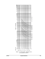
Страница 22: ...1 16 General Information BE1 67 Figure 1 12 Timing Type B1 Short Inverse Drawing Number 99 0932...
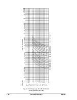
Страница 23: ...BE1 67 General Information 1 17 Figure 1 13 Timing Type B2 Long Inverse Drawing Number 99 0931...
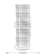
Страница 24: ...1 18 General Information BE1 67 Figure 1 14 Timing Type B3 Definite Time Drawing Number 99 0933...
Страница 25: ...BE1 67 General Information 1 19 Figure 1 15 Timing Type B4 Moderate Inverse Drawing Number 99 0930...
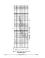
Страница 26: ...1 20 General Information BE1 67 Figure 1 16 Timing Type B5 Inverse Drawing Number 99 0929...
Страница 27: ...BE1 67 General Information 1 21 Figure 1 17 Timing Type B6 Very Inverse Drawing Number 99 0928...
Страница 28: ...1 22 General Information BE1 67 Figure 1 18 Timing Type B7 Extremely Inverse Drawing Number 99 0927...
Страница 29: ...BE1 67 General Information 1 23 Figure 1 19 Timing Type E2 BS 142 Long Inverse Drawing Number 99 1093...
Страница 30: ...1 24 General Information BE1 67 Figure 1 20 Timing Type E4 BS 132 Inverse Drawing Number 99 1094...
Страница 31: ...BE1 67 General Information 1 25 Figure 1 21 Timing Type E5 BS 142 Inverse Drawing Number 99 1095...
Страница 32: ...1 26 General Information BE1 67 Figure 1 22 Timing Type E6 BS 142 Very Inverse Drawing Number 99 1096...
Страница 33: ...BE1 67 General Information 1 27 Figure 1 23 Timing Type E7 BS 142 Extremely Inverse Drawing Number 99 1097...
Страница 35: ...2 2 Human Machine Interface BE1 67 Figure 2 1 BE1 67 Three Phase Relay With Characteristic Angle Control Knob...
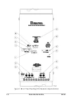
Страница 39: ...2 6 Human Machine Interface BE1 67 Figure 2 3 Location of Assemblies Controls and Indicators...
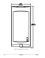
Страница 47: ...4 2 Installation BE1 67 Figure 4 1 Outline Dimensions Front View...
Страница 48: ...BE1 67 Installation 4 3 Figure 4 2 Outline Dimensions Rear View...
Страница 49: ...4 4 Installation BE1 67 Figure 4 3 Outline Dimensions Side View Semi Flush Mounting...
Страница 50: ...BE1 67 Installation 4 5 Figure 4 4 Outline Dimensions Side View Projection Mounting...
Страница 51: ...4 6 Installation BE1 67 Figure 4 5 Panel Drilling Diagram Semi Flush Mounting...
Страница 52: ...BE1 67 Installation 4 7 Figure 4 6 Panel Drilling Diagram Projection Mounting...
Страница 54: ...BE1 67 Installation 4 9 Figure 4 8 Single Phase AC Connections...
Страница 55: ...4 10 Installation BE1 67 Figure 4 9 Three Phase AC Connections...
Страница 56: ...BE1 67 Installation 4 11 Figure 4 10 BE1 67 Single Phase Internal Connection Diagram...
Страница 57: ...4 12 Installation BE1 67 Figure 4 11 BE1 67 Three Phase Internal Connection Diagram...
Страница 62: ...BE1 67 Testing 5 5 Figure 5 3 Blank Polar Graph Form Figure 5 4 Blank Polar Graph Form...


