21
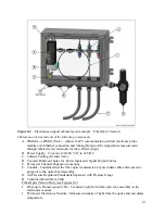
Figure 8-2
– Electronics support cabinet layout example – Fiber Optic Version
Cabinet may not include all of the following components
A.
IFM8-IA or IFM8-I (Mux) – Allows for PC communication with all electronic probe
modules via Ethernet connection and Analog Output of the temperature measurement
through labeled screw terminals for the 4-20mA output.
B.
Power Supply – Converts 120/240 VAC to 24 VDC
C.
Cabinet Cooling Air Inlet Valve
D.
Covered Punch-out holes for Power Input and Signal Output Cables
E.
Pyrometer Channel Expansion Locations
F.
Conduit - Contains either the fiber-optic transmission or power/data cable and routes the
purge air to the optics head assembly.
G.
Air Pressure Regulator/Condensate Separator with Pressure Gauge
H.
Combined Power/Data Cable
Fiber-Optic Version Only (see Figures 8-2)
I.
Fiber-optic Transmission Cable – Transmits light from fiber-optic lens assembly to the
electronics module.
J.
Pyrometer Electronics Module – Measures intensity of light from the optics and calculates
temperature.
Содержание EXACTUS IFM8-I
Страница 4: ...3 Figure 1 2 IFM8 IA Overview...
Страница 10: ...9 c The following screen Figure 4 3 will appear Click the Properties button Figure 4 3...
Страница 15: ...14 Figure 4 10 Check the Echo typed characters locally check box and close the dialog windows Figure 4 11...
Страница 18: ...17 Figure 6 1 Alarm configuration menu Figure 6 2 Pyrometer Internal Temperature Alarm Configuration Menu...


