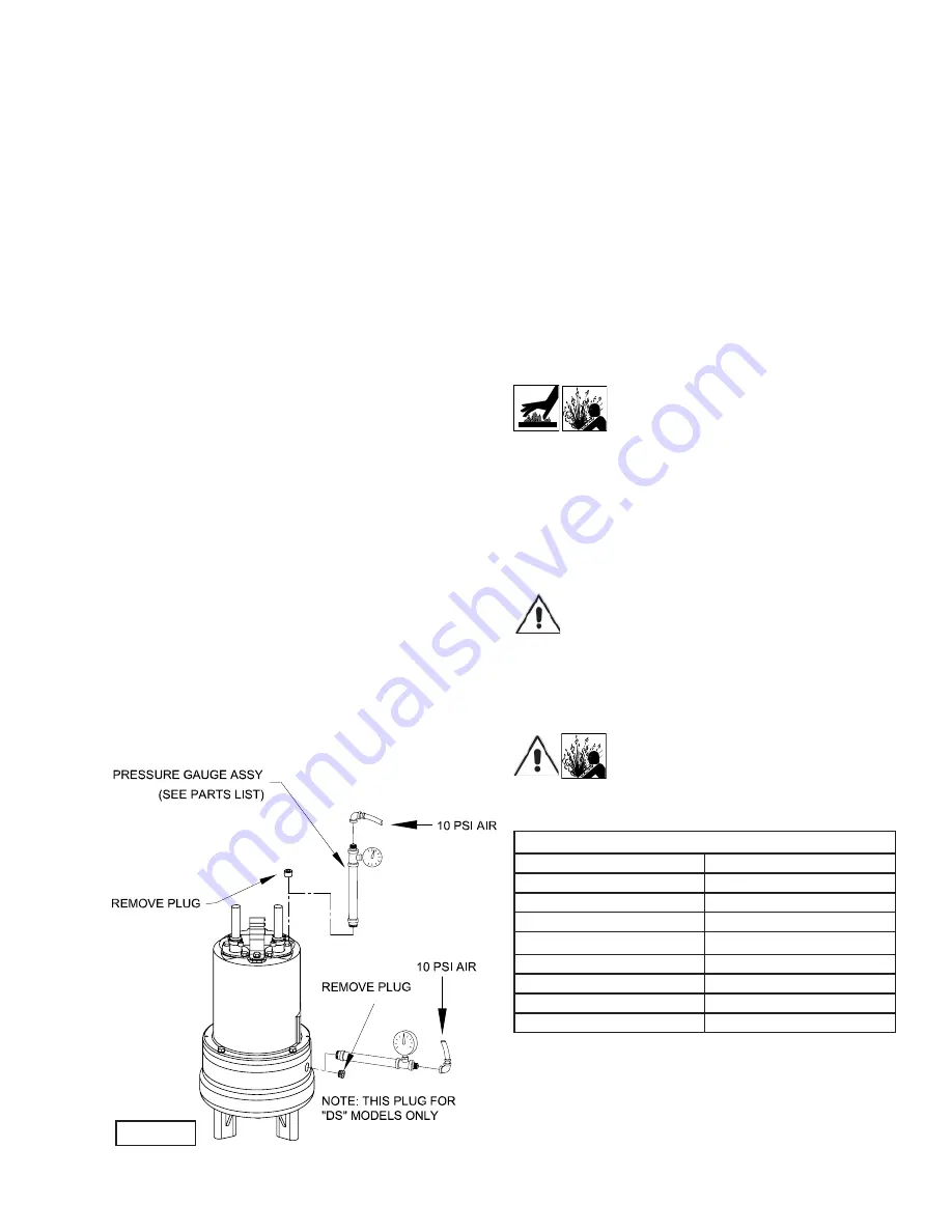
Barnes 4SE-DS series Скачать руководство пользователя страница 9

9

FIGURE 3

F-1.1) Checking Oil:
Motor Housing-

 To check oil, set unit upright. Remove pipe 

plug (39) from housing (6). With a fl ashlight, visually inspect the 
oil in the motor housing (6) to make sure it is clean and clear, 
light amber in color and free from suspended particles. Milky 
white oil indicates the presence of water. Oil level should be just 
above the motor when pump is in vertical position.

F-1.2) Testing Oil:

1.)  Place pump on it’s side, remove pipe plug (39), from motor
 

housing (6) and drain oil into a clean, dry container.

2.)  Check oil for contamination using an oil tester with a
 

range to 30 Kilovolts breakdown.

3.)  If oil is found to be clean and uncontaminated (measuring
 

above 15 KV. breakdown), refi ll the motor housing as per


section F-1.4.

4.)  If oil is found to be dirty or contaminated (or measures
 

below 15 KV. breakdown), the the pump must be carefully


inspected for leaks at the shaft seal (28), cable assemblies


(16) and (56 if used), square ring (27) and pipe plug (39),

 before 

refi lling with oil. To locate the leak, perform a


pressure test as per section F-1.3. After leak is repaired,


dispose of old oil properly, and refi ll with new oil


as per section F-1.4.

F-1.3)  Pressure Test:
Pumps that have been disassembled, Motor Housing-

 If the 

pump has been disassembled, the oil should be drained before 
a pressure test, as described in section F-1.1. Remove pipe 
plug (39) from motor housing (6). Apply pipe sealant to pressure 
gauge assembly and tighten into hole (See Figure 3). Pressurize 
motor housing to 10 P.S.I. Use soap solution around the sealed 
areas and inspect joints for “air bubbles”. 

If, after fi ve minutes, the pressure is still holding constant, and no 
“bubbles” are observed, slowly bleed the pressure and remove 
the gauge assembly. Replace oil as described in section F-1.4. 
If the pressure does not hold, then the leak must be located and 
repaired.

Pumps that have NOT been disassembled, Motor Housing

The pressure test may be done with the oil at its normal level.  
Remove pipe plug (39) from motor housing (6). Apply pipe 
sealant to pressure gauge assembly and tighten into hole (see 
Figure 3). Pressurize motor housing to 10 P.S.I. Use soap 
solution around the sealed areas above the oil level and inspect 
joints for “air bubbles”. For sealed areas below the oil level, 
leaks will seep oil.

If, after fi ve minutes, the pressure is still holding constant, and 
no “bubbles”/oil seepage is observed, slowly bleed the pressure 
and remove the gauge assembly. If the pressure does not hold, 
then the leak must be located and repaired.

Seal Chamber (DS Units Only)-

 Set unit on its side with fi ll 

plug (44) downward, remove plug (44) and drain all oil from 
seal chamber. Apply pipe sealant to pressure gauge assembly 
and tighten into hole in outer seal plate (29). Pressurize seal 
chamber to 10 P.S.I. and check for leaks as outlined above.

CAUTION ! - Pressure builds up extremely 
fast, increase pressure by “TAPPING” air 
nozzle. Too much pressure will damage 
seal. DO NOT exceed 10 P.S.I.

F-1.4)  Replacing Oil:
Motor Housing-

 Set unit upright and refi ll with new cooling oil 

as per Table 1 (see parts list for amount). Fill to just above motor 
as an air space must remain in the top of the motor housing to 
compensate for oil expansion (see Figures 15 & 17). Apply pipe 
thread compound to threads of pipe plug (39) then assemble to 
motor housing (6).

IMPORTANT! - For single phase units, oil level 
should be below capacitor.

Seal Chamber (DS Units Only)-

 Set unit on its side, with plug 

(44) upward, and refi ll with new oil as per Table 1 (see parts 
list for amount). Apply pipe thread compound to threads of pipe 
plug (44) and assemble to outer seal plate (29).

WARNING !  - DO NOT overfi ll oil. 
Overfi lling of motor housing with oil can 
create excessive and dangerous hydraulic 
pressure which can destroy the pump and 

create a hazard. Overfi lling oil voids warranty.

TABLE 1 - COOLING OIL - Dielectric

SUPPLIER

GRADE

BP

Enerpar SE100

Conoco

Pale Paraffi n 22

Mobile

D.T.E. Oil Light

G & G Oil

Circulating 22

Imperial Oil

Voltesso-35

Shell Canada

Transformer-10

Texaco

Diala-Oil-AX

Woco

Premium 100

F-2) Impeller and Volute Service:
F-2.1) Disassembly and Inspection:

To clean out volute (1) or replace impeller (33), disconnect 
power, remove hex bolts (26), and lockwasher (12), vertically 
lift motor and seal plate assembly from volute (1) see Figure 
4. 

Содержание 4SE-DS series

Страница 1: ...product improvement program product changes may occur As such Crane Pumps Systems reserves the right to change product without prior written noti cation 420 Third Street 83 West Drive Bramton Piqua O...

Страница 2: ...7 DOUBLE SEAL CROSS SECTION Fig 17 18 DOUBLE SEAL EXPLODED VIEW Fig 18 19 PARTS LIST 20 22 RETURNED GOODS POLICY 23 WARRANTY 24 START UP REPORT 25 26 WARRANTY REGISTRATION SPECIAL TOOLS AND EQUIPMENT...

Страница 3: ...insert ngers in pump with power connected Always wear eye protection when working on pumps Make sure lifting handles are securely fastened each time before lifting DO NOT operate pump without safety d...

Страница 4: ...l Filled Squirrel Cage Induction Insulation Class B SINGLE PHASE Permanent Split Capacitor PSC Includes overload protection in motor THREE PHASE 200 240 480 is Tri voltage motor 600V Requires overload...

Страница 5: ...out vanes on Back side Dynamically balanced ISO G6 3 Material Cast Iron ASTM A 48 Class 30 SHAFT 416 Stainless Steel SQUARE RINGS Buna N HARDWARE 300 Series Stainless Steel PAINT Air dry enamel top co...

Страница 6: ...n or basin shall be vented in accordance with local plumbing codes This pump is designed to pump sewage ef uent or other nonexplosive or noncorrosive wastewater and shall NOT be installed in locations...

Страница 7: ...ntinuous Amperes Inrush Amperes 110 120 3 00 30 0 220 240 1 50 15 0 440 480 0 75 7 5 600 0 60 6 0 C 4 3 Moisture Sensors DS Models Optional A normally open N O detector is installed in the pump seal c...

Страница 8: ...1 13 7 15 4 14 4 SOW 0 570 14 5 5 49 6 28 4SE1944DS 1 9 480 3 60 1750 B 2 5 7 7 14 4 SOW 0 570 14 5 21 96 24 51 4SE1954DS 1 9 600 3 60 1750 C 1 9 7 2 14 4 SOW 0 570 14 5 34 36 35 60 Winding Resistanc...

Страница 9: ...e gauge assembly and tighten into hole see Figure 3 Pressurize motor housing to 10 P S I Use soap solution around the sealed areas above the oil level and inspect joints for air bubbles For sealed are...

Страница 10: ...ation disassemble volute and impeller as outlined in paragraph F 2 1 If further repair is required remove retaining ring 28d spring 28c and rotating member 28b from shaft see Figures 5 6 Examine all s...

Страница 11: ...tor and Bearing Service F 4 1 Disassembly and Inspection To examine or replace the motor 7 capacitor 9 single phase units controls 56 optional and bearing 25 drain oil from motor as outlined in paragr...

Страница 12: ...ce department Bearings When replacing bearing be careful not to damage the rotor or shaft threads Clean the shaft thoroughly Press bearing 25 on the motor shaft position squarely onto the shaft applyi...

Страница 13: ...ragraph G 2 4 Part description 5 Item part number 6 Quantity required 7 Shipping instructions 8 Billing Instructions G 2 PART NUMBER The part number consists of a six 6 digit number which appears in t...

Страница 14: ...14 FIGURE 13 CONTIUED...

Страница 15: ...Check cutter for freedom of operation security and condition Clean cutter and inlet of any obstruction 9 Loosen union slightly to allow trapped air to escape Verify that turn off level of switch is se...

Страница 16: ...16 FIGURE 15 4SE L Series Single Seal...

Страница 17: ...17 FIGURE 16 4SE L Series Single Seal...

Страница 18: ...18 FIGURE 17 4SE DS Series Double Seal...

Страница 19: ...19 FIGURE 18 4SE DS Series Double Seal...

Страница 20: ...1 034964 Capacitor 30MFD 1 Phase 10 1 039858 Capacitor Bracket 1 Phase 11 4 1 129 1 Hex Hd Cap Screw Std 5 16 18 x 75 Lg Stainless 6 1 129 1 Hex Hd Cap Screw Optional for moisture and temp sensors 12...

Страница 21: ...46TR 4 00 Dia 34 3 005808 Nipple 35 3 003479 Cap 36 1 027344 Gasket 39 1 014270 Pipe Plug 375 NPT ZP 41 A R Loctite242 42 A R Permatex2C 44 1 003217 Pipe Plug All double seal 25 NPT ZP 45 2 5 32 6 Scr...

Страница 22: ...ature Sensor 3 Phase or Moisture Sensor 8 FT 103756A 103741A 103742A 103741A 103740A 15 FT Std 103756 103741 103742 103741 103740 20 FT 103756XA 103741XA 103742XA 103741XA 103740XA 30 FT 103756XC 1037...

Страница 23: ...o Insure That Employees Will Not Be Exposed To Health Hazards In Handling Said Material All Applicable Laws And Regulations Shall Apply IMPORTANT WARRANTY REGISTRATION Your product is covered by the e...

Страница 24: ...guarantees in the nature of performance speci cations furnished in addition to the foregoing material and workmanship warranties on a product manufactured by us if any are subject to laboratory tests...

Страница 25: ...m Does impeller turn freely by hand Yes No Condition of equipment Good Fair Poor Condition of cable jacket Good Fair Poor Resistance of cable jacket Good Fair Poor Resistance of cable and pump motor m...

Страница 26: ...ction Pump Off L1 L2 L2 L3 L3 L1 Voltage supply at panel line connection Pump On L1 L2 L2 L3 L3 L1 Amperage Load connection Pump On L1 L2 L3 FINAL CHECK Is pump seated on discharge properly Check for...

Страница 27: ...CITY STATE ZIP MODEL NO SERIAL NO PART NO BRAND IMPORTANT WARRANTY REGISTRATION Your product is covered by the enclosed Warranty Complete the Warranty Registration Form and return to Crane Pumps Syst...

Страница 28: ...CRANE PUMPS SYSTEMS INC WARRANTY SERVICE GROUP 420 THIRD STREET PIQUA OHIO 45356 U S A FOLD HERE AND TAPE DO NOT STAPLE PLACE STAMP HERE...

Отзывы: