10
Service
Ÿ
Mount hubs on the shaft, leaving
the faces flush with the shaft ends.
Ÿ
Tighten the set screws if the model
has them.
Ÿ
Determine the required clearance
using Table 3. Using a spacer bar
with the obtained thickness, insert
between the hubs at the the same
depth and in 90 ° intervals.
Ÿ
Use a feeler gauge to measure the
gap between the space bar and
hub face. The difference between
the maximum and minimum must
not exceed the specified angular
limit.
Ÿ
Check that the pump-motor
alignment is correct, resting one
square object straight (ruler) at 90°
intervals. Check the clearance with
a feeler gauge.
Ÿ
Proceed to tighten the anchor and
check alignment and clearance
again; if necessary, repeat the
process from the beginning until
you get a proper alignment.
Ÿ
Insert the joint by the clearance
between the hubs and rest it on
any of the covers. Lubricate the
slots and clearance with as much
grease as possible.
Ÿ
Fill the spaces between the grid
and around it with grease. Remove
excess.
Ÿ
Oil the seals to slide on the hubs,
align and assemble the covers,
leaving a displacement of 180 °
between the lubrication holes.
Ÿ
Tighten the screws of the covers
and check for proper assembly of
the seals.
Socket head
set screw
Coupling
hubs
Rubber
spider
Figure 9
"Lovejoy" coupling.
Ÿ
To insert the grid, note that their
segments are radial. To extend as
little as possible, go partially
inserting segments using a soft
mallet. Once the segments are in
position, push them to the bottom
of the grids.
The grid the inner faces (INT) and
external (EXT) are marked for easy
identification.
Ÿ
Fit the covers with the seals (lightly
greased) on the shaft.
1
6
2
3
4
5
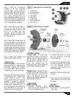
Figure 10 "Steelflex" type F coupling.
1 - Screws, nuts and washers
2 - Cover halves
3 - Gear hubs
4 - Grid members
5 - Gasket
6 - Seal rings
barmesapumps.com


