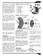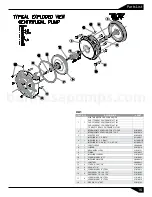
1 - Ceramic seat
2 - Seal seat Buna-N
3 - Inox. retainer
4 - Inox. jacket
5 - Inox. spring
6 - Carbon ring
7 - Elastomer Buna-N
8 - Inox. washer
2
1
3
6
4
5
7
8
Figure 7
Mechanical Seal - Sectional View.
Intermediate
coupling
Shaft
sleeve
Shaft
Seal
stationary
Seal
rotating
member
Seal
spring
Impeller
Impeller
lockwasher
Lockwasher Hex.
screw
Figure 8
Mechanical Seal - Assembly.
09
Service
Step 1: Install the intermediate
coupling if it was previously
removed. Make sure the shaft and
cavities, where will it seats, are clean.
The shaft sleeve should not be sharp,
but a radius of about 1/32”. It is
recommended that lightly polish the
area of the shaft. If the shaft and it
radius are perfectly polished, the seal
can be relatively easily installed.
Step 2: Install the seat assembly (1
and 2) on the inside of the
intermediate coupling, using an SAE
No. 90 oil in rubber parts. This
assembly should be done only
manually, meaning without the use
of an instrument.
Step 3: Install the rotating portion of
the seal without the spring. Lubricate
the shaft and the inside of the seal
with three or four drops of SAE No. 10
oil. With clean, dry hands, insert the
rotating portion to the shaft, sliding
it abuts the stationary seat. Once the
seal is in place, insert the spring (5).
Step 4: Place the impeller and
washers; tighten the hex screw.
Maintenance
Flexible Coupling -
Universal type
pumps generally use 2 different types
of flexible couplings: the "Lovejoy"
type with rubber spider, and the
"Steelflex" type "F" with grids buffer.
The first mentioned coupling requires
no lubrication, the second does
require lubrication at least every
twelve months. If the second type of
coupling is exposed to excessive
moisture, extreme temperatures,
sudden loads applications, etc., it
should be lubricated more often. For
more information on the type of
lubricant consult your distributor.
Flexible Coupling
"Lovejoy" type -
To remove, just
loosen the set screws on the hub. To
reinstall, align the shaft and tighten
the set screws. Should take in
consideration a clearance of 1/16"
(1.574 mm) between jaws. As
mentioned earlier, a good alignment
is essential for optimal operation.
"Steelflex" type -
Identify the parts
in Figure 10. The most relevant issue
in the assembly of a coupling of this
type is the clearance point that
should be left between the hubs; to
determine this see Table 3.
Disassembly
Flexible Coupling
Ÿ
Separate
coupling
covers,
removing the nuts and bolts. Be
sure not to damage the seal.
Ÿ
To remove the grid, use a round
bar or a screwdriver to fit the
curves of the grid.
Ÿ
Insert the tool into the open end of
the grid toward the curved end,
pry out gradually. Alternate
procedure on each side to pop out
half of the grating.
Ÿ
Repeat for each side until it clears
the grid.
Ÿ
If you need to remove the hubs,
loosen the set screws if the model
has them.
Assembly
Flexible Coupling
Ÿ
If the hubs are removed, adjust
shaft shims.
barmesapumps.com


