background image

Manual 2100-694B 

Page 

14 of 62

mode, no auxiliary temperature measurement devices 
are required for operation. The wall-mount unit 
automatically uses a continuous blower setting to 
circulate room air into the return air inlet and uses 
the return air temperature sensor to control room 
temperature.
To change default setpoints, refer to 

Setpoints

 on page 8. 

During installation, the ability to run in orphan mode 
allows deactivation of one of the existing, older wall-
mount units, while keeping the shelter cool with the 
other unit still operating. Once the first of the Bard 
FUSION-TEC HR Series wall-mount units is installed 
and powered on, it will operate in orphan mode—
keeping the climate inside the shelter stable and 
the installers comfortable while the remainder of the 
older equipment is removed and the remaining Bard 
FUSION-TEC HR Series wall-mount units and LV1000 
controller are installed. 
Additionally, should any or all of the FUSION-TEC HR 
Series wall-mount units lose communication with the 
LV1000 controller (such as during maintenance), they 
will continue to serve the shelter’s needs until a repair 
can be made. 

Temperature/Humidity Control

Temperature/Humidity Control Components

Return Air Temperature Sensor

The unit is equipped with a return air temperature 
sensor to monitor the space temperature when the unit 
is in orphan mode. The return air sensor is located 
in the upper part of the return opening in such a way 
that it is exposed to the entering airstream. An alarm 
signal will be sent to the LV controller if the return air 
temperature sensor is disconnected. The temperature is 
measured with a 10k ohm NTC thermistor.
This sensor can be verified and adjusted by:
1.  Press MENU key to go to the Main Menu screen.
2.  Press UP or DOWN keys and ENTER key to enter 

TECHNICIAN password 1313.

3.  Press UP or DOWN keys to scroll to 

I/O Config

press ENTER key.

4.  Press UP or DOWN keys to scroll to 

Return Air 

Sensor C4

; press ENTER key.

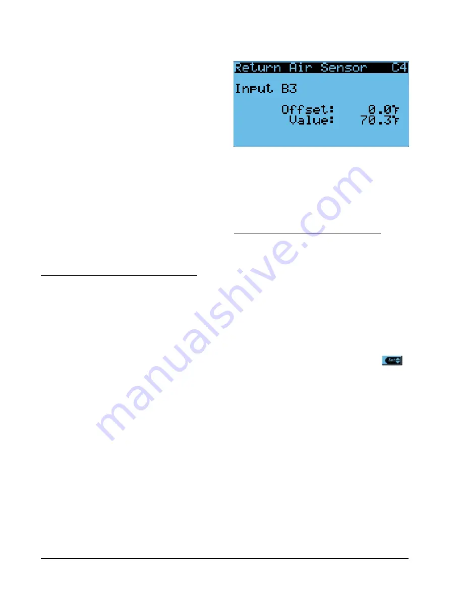
5.  Verify the measurement displayed on screen is 

accurate (see Figure 18). 

6.  If the measurement needs to be adjusted, apply an 

offset value by pressing ENTER to scroll to 

Offset

.

7.  Press UP or DOWN keys to adjust the offset. 
8.  The update will not take effect until the cursor is 

moved out of the 

Offset

 parameter. 

9.  Once adjusted, press the ESCAPE key several 

times to return to Main Menu screen.

Return Air Temperature Alarm

When the return air temperature sensor value is out of 
range (-41.0 to 303.0°F), the controller will generate 
a sensor failure alarm to indicate the sensor is not 
working properly.
This alarm is fixed and cannot be adjusted. 

Temperature/Humidity Control Operation

The unit utilizes a PID control loop for space control. 
This control will compare the space temperature to 
the space setpoint. Based on how far away from the 
setpoint the temperature is, the loop will output a 
cooling or heating capacity number between 0 and 
100%. The unit will then take all of the available 
cooling methods and distribute them evenly across the 
0-100% range. The stages are then brought on as the 
heating or cooling capacity reaches the percentage that 
brings the stages on or off.


There are separate setpoints 

for cooling and heating.
To change or view the unit setpoint:
1.  From the Status screen, press UP or DOWN key 

until Quick Menu displays Setpoints icon (          ). 
Press ENTER key.

2.  Press ENTER key to scroll to 

Cooling

 or 

Heating 

(see Figure 4 on page 8).

3.  Press UP or DOWN keys to change the value to 

desired heating and/or cooling setpoint.

Cooling

The unit is equipped with 1 stage of freecooling and 2 
stages of mechanical cooling (compressor and solenoid) 
for a total of 3 cooling stages (see Figure 19).

Cooling w/No Economizer

The unit is equipped with 1 stage of freecooling and 
2 stages of mechanical cooling (compressor and 
solenoid). However, the outdoor conditions are not 
favorable for economizer operation so there are a total 
of 2 cooling stages (see Figure 20).

Heating

The unit is equipped with 1 stage of electric heat (see 
Figure 21).

FIGURE 18

Adjusting Return Air Sensor

Содержание FUSION-TEC HR35BPA

Страница 1: ...6 www bardhvac com Manual 2100 694B Supersedes 2100 694A Date 2 14 20 NOTE LV1000 controller is required for operation when HR BP units are used SERVICE INSTRUCTIONS FUSION TEC WALL MOUNT AIR CONDITIO...

Страница 2: ...ndoor Airflow Operation 23 Blower Speed Control 23 Additional Indoor Airflow Alarms 23 Supply Air Temperature Alarm 23 Condenser Fan 23 Condenser Fan Components 23 Condenser Fan 23 Liquid Line Pressur...

Страница 3: ...Verifying Condenser Fan Output 23 Figure 35 Fan Blade Setting 23 Figure 36 Adjusting Discharge Liquid Transducer Pressure Values 24 Figure 37 Voltage to Pressure Discharge Liquid Pressure Transducer...

Страница 4: ...the installation is made See Additional Publications for information on codes and standards Sizing of systems for proposed installation should be based on heat loss and heat gain calculations made ac...

Страница 5: ...s to be limited to the most extreme situations DANGER signs should not be used for property damage hazards unless personal injury risk appropriate to these levels is also involved WARNING Indicate s a...

Страница 6: ...ewed and adjusted from the TEC EYE display The program and operating parameters are permanently stored on FLASH MEMORY in case of power failure The TEC EYE connects to the wall mount unit control boar...

Страница 7: ...taking measures to decrease humidity without using extra energy Active Dehum Unit is taking active measures to decrease humidity Self Test Unit is performing a self test Off by Alarm Unit has major fa...

Страница 8: ...when the desired icon is displayed FIGURE 3 Quick Menu Icons Alarm Log Information Setpoints NOTE Screenshots shown in this manual reflect default settings when applicable Quick Menu Setpoints From t...

Страница 9: ...period see Figure 8 FIGURE 8 Last 24 Hour Operation Software Version The Software Version screen displays the model number of the unit as well as all software version information for the PLC see Figu...

Страница 10: ...ld verify system pressures temperatures condenser fan operation and EEV operation Stage 2 Cooling Full load compressor operation is under test Technician should verify system pressures temperatures co...

Страница 11: ...s 1 Press MENU key to go to the Main Menu screen 2 Use UP or DOWN keys and ENTER key to enter ENGINEER password 9254 3 Press UP or DOWN keys to scroll to Settings press ENTER key 4 Press UP or DOWN ke...

Страница 12: ...alarm screen To clear all alarms navigate to the screen at the end of the alarm list shown in Figure 13 and press and hold the ALARM key for 3 seconds OPERATION FIGURE 13 Clearing All Alarms Clearing...

Страница 13: ...overcool the indoor space due to the HVAC system s incapability to overcome the outdoor conditions To change the reset and disable type 1 Press MENU key to access the Main Menu screen 2 Press UP or DO...

Страница 14: ...o Return Air Sensor C4 press ENTER key 5 Verify the measurement displayed on screen is accurate see Figure 18 6 If the measurement needs to be adjusted apply an offset value by pressing ENTER to scrol...

Страница 15: ...10 120 Compressor Stage 2 FIGURE 20 Cooling w No Economizer Compressor Stage 1 10 20 30 40 50 60 70 80 90 100 10 0 110 120 Compressor Stage 2 Off Deadband On Deadband sometimes called a neutral zone o...

Страница 16: ...Service Instructions 2100 673 for adjustment of the dehumidification setpoint and differentials FIGURE 23 Overriding EEV Output Electronic Expansion Valve EEV EEV Components Electronic Expansion Valve...

Страница 17: ...and Subcooling on EEV 1 Circuit Suction Pressure Transducer The unit has a pressure transducer installed on the suction line between the evaporator coil and compressor The transducer is used for syste...

Страница 18: ...larm Setup A7 press ENTER key 5 Press ENTER key to scroll to Setpoint see Figure 28 6 Press UP or DOWN keys to change to the desired value 7 Press ENTER key to save the value scroll to Delay 8 Press U...

Страница 19: ...8 0 v 10 0 v 1200 1620 Heating 41 0 4 1 v 900 Dehumidification Mode 20 0 2 0 v 500 EEV Operation EEV Superheat Control The electronic expansion valve EEV will modulate to maintain a specific superheat...

Страница 20: ...v 1335 Economizer Standard Economizer High S T 45 0 75 0 4 5 v 7 5 v 1600 1950 Heating 35 0 3 5 v 1335 Dehumidification Mode 35 0 3 5 v 1335 TABLE 8 Indoor Blower Performance Speed High Low ESP Inch H...

Страница 21: ...l Dirty Filter Switch These units are equipped with a differential pressure switch to indicate when the filter s needs to be replaced see Figure 30 The dirty filter switch measures the pressure differ...

Страница 22: ...tic Setting 0 40 0 50 0 60 0 70 0 75 0 80 0 90 1 00 Evaporator Airflow 100 98 7 98 1 97 5 91 7 81 3 79 1 78 6 HR58BP Standard Airflow Switch Static Setting 0 30 0 35 0 40 0 45 0 50 0 65 0 70 0 90 Evap...

Страница 23: ...not be adjusted Condenser Fan Condenser Fan Components Condenser Fan The unit is equipped with a condenser fan that is driven by an electronically commutated motor ECM This fan is controlled by a 0 10...

Страница 24: ...be adjusted apply an offset value by pressing the ENTER key to scroll to Offset 7 Press UP or DOWN keys to adjust the offset The update will not take effect until the cursor is moved out of the offse...

Страница 25: ...eed At lower ambient outdoor temperatures this may cycle regularly as normal operation In some cases in higher wind prone areas the condenser fan may stay off for prolonged durations due to low liquid...

Страница 26: ...itoring allows for a lockout condition in a situation where the switch is open If the high pressure switch opens the CCM will de energize the compressor If the switch closes it will then restart the c...

Страница 27: ...the wall mount unit receives a signal from the compressor control module CCM indicating a high pressure event the wall mount unit will generate an alarm Upon receiving the alarm the wall mount unit w...

Страница 28: ...key to scroll to Comp Limit see Figure 41 6 Press UP or DOWN keys to change Comp Limit value 7 Press ENTER key to save value and move cursor to Cutoff Temp 8 Press UP or DOWN keys to adjust the temper...

Страница 29: ...s override will last for 5 minutes or until the Override is changed back to Disabled Dust Sensor The unit has a dust sensor installed in the outdoor air inlet next to the outdoor air sensor The dust s...

Страница 30: ...capability to cool Damper Blade The system utilizes three damper blades used to bring in outdoor air and exhaust space air for economizer operation The damper blades are made of sheet metal and are i...

Страница 31: ...TC thermistor The humidity is measured with a humidity sensor that outputs a 4 20mA signal to the controller The outdoor temperature can be verified by 1 Press MENU key to go to the Main Menu screen 2...

Страница 32: ...ied by 1 Press MENU key to go to the Main Menu screen 2 Press UP or DOWN keys and ENTER key to enter TECHNICIAN password 1313 3 Press UP or DOWN keys to scroll to I O Config press ENTER key 4 Press UP...

Страница 33: ...for emergency purposes The second mode is Dry Bulb where the outdoor temperature is the only consideration for economizer use on a free cooling call The third mode is TempHum where the outdoor temper...

Страница 34: ...l only using any of the previously mentioned modes a 0 10v analog signal will be sent to the economizer actuator Regardless of economizer only or optimized cooling mode the actuator will then open and...

Страница 35: ...e LV NOTE Units with a B in the vent package position in the model number will still open the economizer in emergency vent mode Emergency Off If the supervisory controller Emergency Off input becomes...

Страница 36: ...These devices are used with the Bard Guard BG1000 anti theft controller to provide an anti theft measure These sensors and switch form a loop that when connected to the BG1000 controller will cause t...

Страница 37: ...el Finish 8 Dark Bronze Baked Enamel Finish PLACEHOLDER X Future Use COIL AND UNIT COATING OPTIONS X Copper Aluminum Evaporator Coil Copper Aluminum Condenser Coil 1 Coated Evaporator Coil 2 Coated Co...

Страница 38: ...ow 83 ohms 24VAC Hot 24VAC Common Unit Disable Dirty Filter Switch Compressor Alarm Relay Micro USB Damper Blade Switch Airflow Switch Digital Ground Liquid Line Temp Sensor Outdoor Air Temp Sensor Re...

Страница 39: ...Analog Input 0 5VDC B7 Suction Temperature Sensor Analog Input 10K Ohm Curve J GND Analog Ground VDC 24VDC to Outdoor Humidity Sensor B8 Liquid Pressure Transducer Analog Input 5VDC 4 5VDC B9 Suction...

Страница 40: ...to insure optimal system performance Refer to instructions for the cylinder that is being utilized for proper method of liquid extraction Safety Practices 1 Never mix R 410A with other refrigerants 2...

Страница 41: ...529 155 563 157 598 HR58 75 62 Low Side High Side 129 318 130 340 131 365 132 389 133 414 134 440 136 467 137 495 137 527 139 553 140 584 80 67 Low Side High Side 138 326 139 349 140 374 141 399 142 4...

Страница 42: ...an individual unit to be disconnected from the Bard Guard security system for an extended period of service time longer than the maximum 250 minutes disarm time place a jumper across the appropriate...

Страница 43: ...he J13 connector The thermocouple wires are loose in the sensor housing and require a butt splice connector or wire nut to connect FIGURE 56 8301 067 Sensor Electrical Connections FIGURE 57 8301 067 S...

Страница 44: ...d or local weather data to find ambient temperature conditions FIGURE 58 8301 067 Sensor Temperature Probe Troubleshooting 4 Using an ohmmeter or resistance mode on a multimeter measure resistance acr...

Страница 45: ...39 3 9 24 676 40 4 4 24 063 41 5 0 23 467 42 5 6 22 887 43 6 1 22 323 44 6 7 21 775 45 7 2 21 242 46 7 8 20 724 47 8 3 20 220 48 8 9 19 730 49 9 4 19 253 50 10 0 18 789 Temperature Resistance F C 51...

Страница 46: ...for the humidity sensor to return to normal operation FIGURE 59 8301 067 DIP Switch Output Configuration FIGURE 60 8301 067 Sensor Humidity Probe Troubleshooting 8301 067 Outdoor Humidity Sensor Troub...

Страница 47: ...20 78 16 480 79 16 640 80 16 800 81 16 960 82 17 120 83 17 280 84 17 440 85 17 600 86 17 760 87 17 920 88 18 080 89 18 240 90 18 400 91 18 560 92 18 720 93 18 880 94 19 040 95 19 200 96 19 360 97 19 5...

Страница 48: ...0 55 0 65 0 75 0 90 Evaporator Airflow 100 99 7 98 7 96 8 96 0 94 4 91 6 85 2 HR36BP Default High S T Switch Static Setting 0 12 0 12 0 12 0 20 0 20 0 35 0 35 0 40 Evaporator Airflow 100 99 3 99 4 98...

Страница 49: ...in insulation exposing bare wire C If communication cable is damaged i Replace communication cable D If communication cable is not damaged i Carefully reconnect the dust sensor communication cable to...

Страница 50: ...83 240 3 88 243 3 93 246 3 98 249 4 03 252 4 08 255 4 13 258 4 17 261 4 22 264 4 27 267 4 32 270 4 37 273 4 42 276 4 47 279 4 51 282 4 56 285 4 61 288 4 66 291 4 71 294 4 76 297 4 81 300 4 85 303 4 9...

Страница 51: ...e dust sensor communication cable from the dust sensor connector on the dust sensor alarm board and the dust sensor B Inspect communication cable for the following i Wires pulled out of the connectors...

Страница 52: ...2 36 1 86 37 1 91 38 1 96 39 2 01 40 2 06 41 2 11 42 2 16 43 2 21 44 2 26 45 2 31 46 2 35 47 2 40 48 2 45 49 2 50 50 2 55 51 2 60 52 2 65 53 2 70 54 2 75 55 2 80 56 2 84 57 2 89 58 2 94 59 2 99 60 3 0...

Страница 53: ...13 474 103 39 4 5446 10 23 3 118 108 28 2 2 36 583 66 18 9 13 137 104 40 0 5326 9 22 8 114 272 29 1 7 35 548 67 19 4 12 810 105 40 6 5208 8 22 2 110 575 30 1 1 34 545 68 20 0 12 492 106 41 1 5094 7 21...

Страница 54: ...8 113 45 4656 114 8 46 4490 116 6 47 4332 118 4 48 4180 120 2 49 4034 122 50 3893 123 8 51 3759 125 6 52 3629 127 4 53 3505 192 2 54 3386 131 55 3271 132 8 56 3160 134 6 57 3054 136 4 58 2952 138 2 59...

Страница 55: ...285 295 20 1 2 315 300 20 4 2 346 305 20 8 2 377 310 21 1 2 408 315 21 4 2 439 320 21 8 2 469 325 22 1 2 500 Pressure Signal PSI Bar Vdc 330 22 5 2 531 335 22 8 2 562 340 23 1 2 592 345 23 5 2 623 35...

Страница 56: ...2 324 116 7 9 2 356 118 8 0 2 388 120 8 2 2 420 122 8 3 2 452 124 8 4 2 484 126 8 6 2 516 Pressure Signal PSI Bar Vdc 128 8 7 2 548 130 8 8 2 580 132 9 0 2 612 134 9 1 2 644 136 9 3 2 676 138 9 4 2 7...

Страница 57: ...terminal 20 on the DIN rail A Measurement should be close to 5 VDC B If VDC is correct move to step 12C If not measure from Y1 to GND on PLC board If not close to 5 VDC replace the PLC board C If meas...

Страница 58: ...GURE 67 DEC Star Blower Control Module Bolt Removal 20 Remove the screws from the blower control module assembly so back plate can be removed 21 Unplug the motor from the module Measure resistance bet...

Страница 59: ...eps from Figure 68 1 Phase A to Phase C 2 Phase A to Phase B 3 Phase B to Phase C 4 Phase A to Ground 5 Phase B to Ground 6 Phase C to Ground 22 Resistance should be equal and none should be grounded...

Страница 60: ...PLC and terminal 20 on the DIN rail A Measurement should be close to 5 VDC B If VDC is correct move to step 12C If not measure from Y1 to GND on PLC board If not close to 5 VDC replace the PLC board C...

Страница 61: ...plug and then all three phases and the motor chassis see Figure 72 on page 62 FIGURE 70 Testing Voltage on Blower Motor 6 Pin Plug FIGURE 71 FASCO Blower Control Module Bolt Removal TABLE 24 FASCO Te...

Страница 62: ...l 2100 694B Page 62 of 62 FIGURE 72 FASCO Motor Plug Testing 21 Resistance should be equal and none should be grounded A If this fails replace the blower assembly B If it passes replace the control mo...

Отзывы: