Installation
15
Video connection
The display accepts 3 different video formats: DVI-I, VGA (analog) and
BNC (analog, only for monochrome video signals).
You can connect one or all of these inputs.
If more than 1 input is connected you can switch inputs by using the
display’s on-screen display.
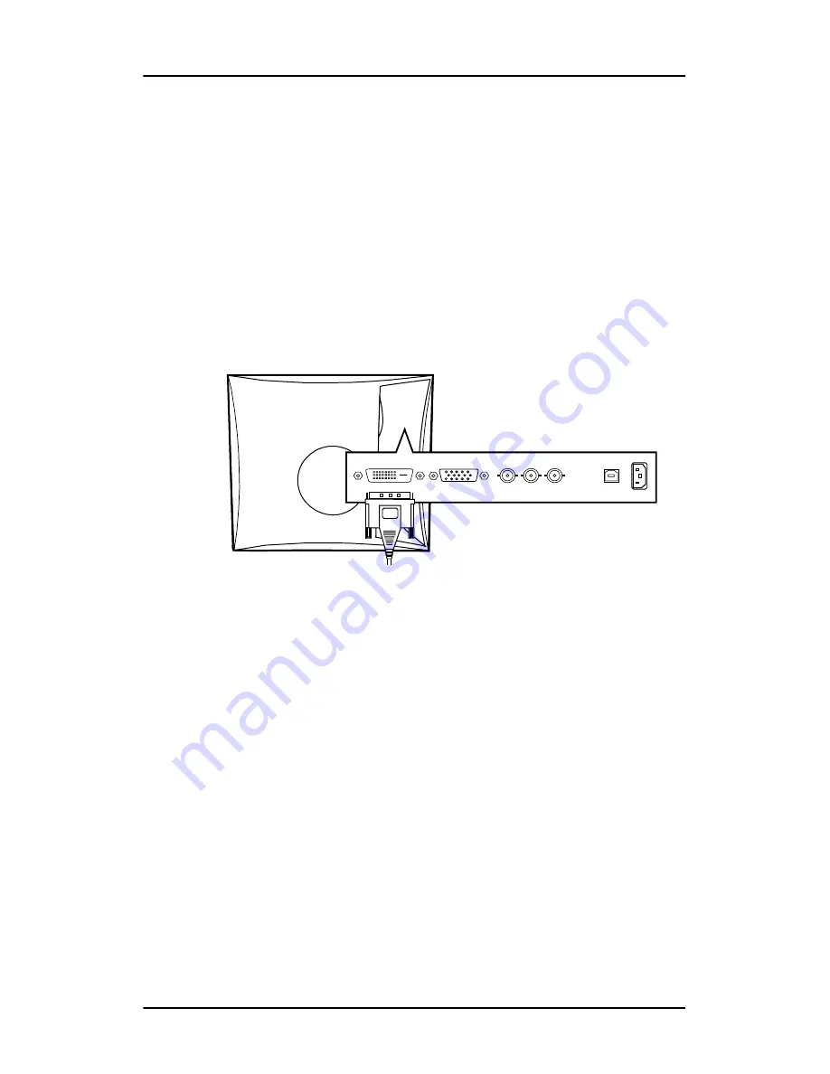
Connecting DVI signals
1.
Connect one end of the DVI cable to the DVI input of the display.
Figure 5
2.
Connect the other end of the DVI cable to the DVI connector of the
signal source.
Connecting analog video to the VGA connector
Proceed as follows:
1.
Connect one end of the VGA cable to the D15 input of the display.
Содержание MVGD 1318 CR/ER
Страница 1: ...Installation User Manual MVGD 1318 CR ER ...
Страница 2: ... This page intentionally left blank 2 This page intentionally left blank ...
Страница 58: ...Warranty Statement 58 ...
Страница 59: ...www barco com K5904082 01 October 2006 ...