background image

R5906790 /04

Athena

31

S C R E E N  C E N TE R

S C R E E N  C E N TE R

O

F

F

-C

E

N

T

E

R

A

B

Image 5-2

3.

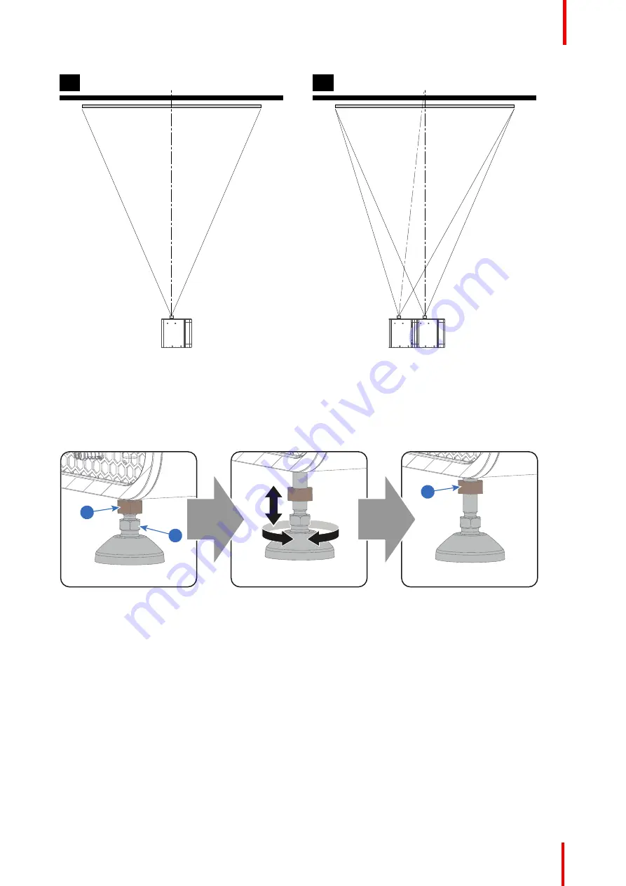
Proceed to level the projector by adjusting the feet of the projector as follows:

Loosen the nut (1) on the threaded rod of the three projector feet. Use a 17mm open wrench.

Adjust the height of the 3 legs to level the projector. Use a 14 mm wrench to adjust the height as illustrated
(2).

Secure the leg height by tightening the nuts (1) of each projector foot.

1

2

1

Image 5-3

4.

Later, when the projector is up-and-running, adjust precise image geometry and placement.

Projector tilting

In an ideal installation, the Athena lens surface is

centered with

and

parallel to

the screen. This orientation

helps to ensure optimized lens performance with minimal offset. If this position is not possible (such as when
the projector is significantly higher than the center of the screen), it is better to rely on

offset

rather than extra

tilt

. In other words, use the SHIFT functionality of the Lens Holder prior to tilt the projector.

1.

Before adjusting tilt, make sure the projector is as well-centered with the theatre screen as possible for the
installation area.

2.

Check the degree of screen tilt, or measure this incline with a protractor at the screen.

3.

Tilt the projector to closely match this screen tilt angle as follows:

Loosen the nut (1) on the threaded rod of the three projector feet. Use a 17mm open wrench.

Adjust the height of the 3 legs until the projected image matches the projection port window and the screen
tilt. Use a 14mm open wrench to adjust the height as illustrated (2).

Physical installation

Содержание Athena

Страница 1: ...ENABLING BRIGHT OUTCOMES Installation manual Athena ...

Страница 2: ...Barco Visual Beijing Electronics Co Ltd 地址 北京市 昌平区 中关村科技园 昌平园 昌盛路 16号 www barco com en support www barco com Barco NV Beneluxpark 21 8500 Kortrijk Belgium www barco com en support www barco com ...

Страница 3: ...ncerns or to report security issues with Barco products please inform us via contact details mentioned on https www barco com psirt To protect our customers Barco does not publically disclose or confirm security vulnerabilities until Barco has conducted an analysis of the product and issued fixes and or mitigations Federal Communications Commission FCC Statement This equipment has been tested and ...

Страница 4: ...rties guaranteed in writing or due to the intent or gross negligence or part of Barco If the purchaser or a third party carries out modifications or repairs on goods delivered by Barco or if the goods are handled incorrectly in particular if the systems are operated incorrectly or if after the transfer of risks the goods are subject to influences not agreed upon in the contract all guarantee claim...

Страница 5: ...ess overview 26 5 Physical installation 29 5 1 Positioning the Athena at port window 30 5 2 Connecting the projector with the power net 32 5 3 Connecting a UPS to the projector electronics 33 6 Lenses Lens selection 37 6 1 Available lenses 38 6 2 Lens selection 38 6 3 Lens installation 39 6 4 Mounting the lens safety cable 41 6 5 Lens removal 42 6 6 Lens shift zoom focus 43 7 Input Communication 4...

Страница 6: ...ace 95 10 Starting up 97 10 1 Switching the Athena ON 98 10 2 Switching the Athena OFF 99 11 Scheimpflug 101 11 1 Scheimpflug introduction 102 11 2 Scheimpflug adjustment 103 11 3 Fixation of the Lens Holder front plate 106 11 4 Back Focal Length adjustment 107 12 Convergence 111 12 1 Convergence controls 112 12 2 Preparing for convergence adjustment 113 12 3 Converging the blue pattern onto the r...

Страница 7: ...n of the right side cover 146 16 11 Installation of the left side cover 147 16 12 Installation of the top cover 148 16 13 Installation of the rear cover 149 16 14 Installation of the front cover 150 A Specifications 153 A 1 Specifications of the Athena 154 A 2 Specifications of the ICMP 156 A 3 Specifications of the ICMP X 157 A 4 Dimensions of the Athena 158 A 5 Dimensions of the universal pedest...

Страница 8: ...R5906790 04 Athena 8 ...

Страница 9: ...ur every expectation and that you thereby take a little time to page through this important manual Familiarizing yourself with it s features important safety instructions and necessary maintenance actions will ensure you enjoy many years of reliable trouble free high quality performance Overview About this manual R5906790 04 Athena Welcome 1 ...

Страница 10: ...ed from you For your safety and in the interest of reliable trouble free high quality performance we urge the user operator service technician to follow all instructions precisely Follow the maintenance recommendations and procedures in this manual step by step to keep your projector in excellent condition Doing so will directly impact the lifetime of your Athena If after having read over these in...

Страница 11: ... cautions as well Clarification of the term Athena used in this document When referring in this document to the term Athena means that the content is applicable for following Barco products ATHENA Barco provides a guarantee relating to perfect manufacturing as part of the legally stipulated terms of guarantee Observing the specification mentioned in this chapter is critical for projector performan...

Страница 12: ...ss to live parts Safety standards also impose limits to the internal and external temperature rises radiation levels mechanical stability and strength enclosure construction and protection against the risk of fire Simulated single fault condition testing ensures the safety of the equipment to the user even when the equipment s normal operation fails Owner s record The part number and serial number...

Страница 13: ...D shall be taken into account See Light beam Hazard Distance HD page 16 2 3 Important safety instructions To prevent the risk of electrical shock Installation according to the local electrical code and regulations by qualified technical personnel only A readily accessible disconnect device must be incorporated externally to the equipment for removal of the power to the projector cord Warning High ...

Страница 14: ...ng the projector The lamp used in the projector contains mercury In case of a lamp rupture explosion there will be a mercury vapor emission In order to minimize the potential risk of inhaling mercury vapors Ensure the projector is installed only in ventilated rooms Replace the lamp module before the end of its operational life Promptly ventilate the room after a lamp rupture explosion has occurred...

Страница 15: ...ntrols or to change other control settings not specially discussed in this manual can lead to permanent damage to the projector and cancellation of the warranty Remove all power from the projector and refer servicing to qualified service technicians under the following conditions When the power cord or plug is damaged or frayed If liquid has been spilled into the equipment If the product has been ...

Страница 16: ...ens Throw Ratio TR To protect untrained users the installation shall comply with the following installation requirements light output levels in excess of the limits shall not be permitted at any point less than 2 0 meters SH Image 2 1 above any surface upon which persons are assumed to stand or 1 meter SW Image 2 1 below or in lateral separation from any place where such persons are assumed to be ...

Страница 17: ...atio TR TR Throw Ratio The ratio of the distance to the screen throw to the screen width Hazard Distance HD m TR 0 0 2 0 4 0 6 0 8 1 1 2 1 0 1 2 1 4 1 6 1 8 2 0 2 2 2 4 2 6 2 8 3 0 3 2 3 4 3 6 3 8 4 0 4 2 4 4 4 6 Image 2 3 HD in meter in function of the Throw Ratio TR Safety ...

Страница 18: ...ith mild soap and water Personal protection rules Handle the cleansing agent in a well ventilated area Do not eat drink or smoke during use Wear gloves Butyl rubber PVC and goggles Wear suitable protection clothing WARNING Before handling Hazardous Chemicals ensure that you have read and understood the safety instructions provided by the supplier of the chemical in the Safety Data Sheet Safety Dat...

Страница 19: ...nsideration of things such as image size ambient light level projector placement and type of screen to use are critical to the optimum use of the projection system Barco provides a guarantee relating to perfect manufacturing as part of the legally stipulated terms of guarantee Observing the specification mentioned in this chapter is critical for projector performance Neglecting this can result in ...

Страница 20: ...ll be solved by one of the following non limitative product installation measures Create more separation distance between projector and interfered device Change direction of the interfered device Electromagnetic shielding of the projection booth No interference to radio communication in neighbor buildings possible if a separation distance of 30 m 32 8 yards is provided Cooling requirements The pro...

Страница 21: ...nd the UPS inlet of the projector must be done with a certified AC power supply cord of minimum 0 75 mm or 18 AWG and minimum 300V WARNING Disconnect the power cord for removal of all power from the unit The Athena does not have a built in UPS unit Projector weight Do not underestimate the weight of the Athena The projector weights approximately 53 kg 116 8 lb without lens Ensure that the pedestal...

Страница 22: ...e small box 3 between the polystyrene foam on top of the projector This box contains the product documentation manuals etc 4 Remove the polystyrene foam 4 from the top of the projector 2 3 4 Image 3 3 5 Open the plastic bag and lift the projector out of its packaging using the handles provided in the projector base Getting started ...

Страница 23: ...sible The packaging of the Athena is provided with a shock watch label If this shock watch label was triggered red colored at arrival during transport may indicate rough handling by the transport company In this case the instructions mentioned on the label should be followed which are adding a note on the bill of lading and informing the transport company and the Barco sales and service office as ...

Страница 24: ...hipping to ensure that the system was not compromised before reaching the customers final destination These tamper labels can be found on the top cover plate from the Light Processor compartment the side cover plate from the Light Processor compartment on the internal cover of the card cage and on the ICMP See chapter Removal and installation of the projector covers page 137 for instructions on ho...

Страница 25: ...r Athena up and running Each stage is briefly described and refers to more detailed step by step procedures in this manual Use this overview as a checklist to ensure that all stages have been followed in the setup process of the Athena Let the projector acclimatize to ambient conditions after unpacking Neglecting this may result in a startup failure of the light processor unit Overview Installatio...

Страница 26: ...Place the ON OFF switch of the projector in the I position As a result the projector starts to initialize The status lights of the projector lights up GREEN once the projector is initialized In case the status lights up RED may indicate a tamper event during transport If so contact Barco customer service 10 Select the corresponding lens parameters for the installed lens See user guide of the Commu...

Страница 27: ...user guide of the Communicator Touch Panel for more detailed information In case the projector is equipped with a HD SDI input module apply a single or dual channel SMPTE HD SDI source to the input ports of the HD SDI input module and start up the projector Use the Communicator Touch Panel to configure the applied source See the user guide of the Communicator Touch Panel for more detailed informat...

Страница 28: ...R5906790 04 Athena 28 Installation process ...

Страница 29: ...ow the mechanical and electrical set up of your Athenahas to be done Overview Positioning the Athena at port window Connecting the projector with the power net Connecting a UPS to the projector electronics R5906790 04 Athena Physical installation 5 ...

Страница 30: ...p of the projector The universal pedestal support 19 rack systems projector peripherals such as alternative content switchers ShowVault etc Required tools 14mm open end wrench 17mm open end wrench Projector centering 1 If the projector is standalone in front of the port window center the projector with the theatre screen A 2 If an analog film projector is already present projector will be off cent...

Страница 31: ...ensure optimized lens performance with minimal offset If this position is not possible such as when the projector is significantly higher than the center of the screen it is better to rely on offset rather than extra tilt In other words use the SHIFT functionality of the Lens Holder prior to tilt the projector 1 Before adjusting tilt make sure the projector is as well centered with the theatre scr...

Страница 32: ...ector with the power net WARNING The total electrical installation should be protected by an appropriate rated and readily accessible disconnect switch circuit breakers and ground fault current interrupters The installation shall be done according to the local electrical installation codes CAUTION The cross sectional area of the conductors in the Power Supply Cord shall be not less than 1mm2 16AWG...

Страница 33: ...the projector electronics WARNING Only use UPS units which are suitable for the Athena series projector See chapter Installation requirements for more information about the requirements of the UPS Required tools 3mm Allen wrench How to connect the UPS 1 Remove the right side cover of the projector See procedure Removal of the right side cover page 142 2 Remove the rear cover See Removal of the rea...

Страница 34: ... 7 5 Install the SMPS cover and install the 2 screws Use a 3mm Allen wrench 6 Install the rear cover See Installation of the rear cover page 149 7 Install the UPS according to the instructions of the manufacturer and the local regulations 8 Connect the power output cord from the UPS unit to the UPS inlet socket 5 of the projector Physical installation ...

Страница 35: ...f the projector See procedure Installation of the right side cover page 146 CAUTION The electrical connection with the UPS INLETsocket of the projector must be done with a certified AC power supply cord minimum 0 75 mm or 18 AWG and minimum 300V Physical installation ...

Страница 36: ...R5906790 04 Athena 36 Physical installation ...

Страница 37: ...he projector with a Lens mounted in the Lens Holder Always remove the Lens before transporting the projector Neglecting this can damage the Lens Holder and Prism CAUTION Caution when removing or installing the lens Fragile parts at the inner side of the Lens Holder Each time a lens is manipulated e g removed and installed in a projector it needs to be homed and returned Overview Available lenses L...

Страница 38: ... 2 1 7 B R9856521 1 34 1 9 Image 6 2 M R9856522 1 5 2 15 Image 6 3 M R9856523 1 7 2 55 Image 6 4 M R9856524 2 3 9 Image 6 5 M R98565241 2 09 3 9 F Image 6 1 0 69 DC2K zoom lens 1 2 1 7 R9856520 Image 6 2 0 69 DC2K zoom lens 1 34 1 9 R9856521 Image 6 3 0 69 DC2K zoom lens 1 5 2 15 R9856522 Image 6 4 0 69 DC2K zoom lens 1 7 2 55 R9856523 Image 6 5 0 69 DC2K zoom lens 2 3 9 R9856524 6 2 Lens selectio...

Страница 39: ...taken into account 6 3 Lens installation How to install a lens into the Lens Holder 1 Remove the foam rubber in the opening of the Lens Holder if not removed yet 2 Take the lens assembly out of its packing material and remove the lens caps on both sides Caution Do not touch the glass of the lens 3 Ensure that the Lens Holder stands in the On Axis position horizontal and vertical mid position 4 Pla...

Страница 40: ...t in less wear of the Lens Holder 7 Check if the lens is really secured by trying to pull the lens out of the Lens Holder 8 Activate the corresponding lens parameters for the installed lens See user guide of the Communicator chapter Installation Advanced Lens parameters Caution Not using the correct lens parameters could result in lens damage Image 6 8 9 Perform a lens HOME RETURN operation See us...

Страница 41: ...ke sure the lens is really secured by trying to pull the lens out of the lens holder 2 Hook the shackle lock with cable around the feet of the projector 3 For lenses with a flat barrel 1 Place the lens with lens safety cable 1 in the lens holder Make sure the safety cable is properly mounted around the lens 2 Strap the cable so that the gap between the lens and the cable is smaller then 0 4 mm Len...

Страница 42: ...lder 1 Support the lens with one hand while you unlock the lens holder by sliding the lock handle 1 towards the unlocked position as illustrated 2 Gently pull the lens out of the lens holder maintaining its coaxial direction Caution Do not accidentally bump with the lens against the electronic boards inside the Lens Holder 1 Image 6 11 Lenses Lens selection ...

Страница 43: ...ue to mechanical and optical limitations the shift range is limited as well All lenses have a shift range of 50 up 50 down 30 left and 30 right This range is valid for all throw ratios Within these shift ranges the projector and lens perform excellently Configuring the projector outside these shift ranges will result in a slight decline of image quality U D SIDE VIEW P F TOP VIEW P F L R 50 50 30 ...

Страница 44: ...rojection lenses used with high brightness projectors The operation temperature of the lens is reached after approximately 30 minutes projection of average video Button backlight colors BLUE The default backlight color of the Shift Zoom and Focus buttons is blue which indicates that the button is enabled PURPLE When pushing the Shift Zoom or Focus button the backlight color is purple of the part o...

Страница 45: ...and communication ports of your Athena Note that all information about the ICMP X is gathered into one separated chapter ICMP X page 59 Overview Introduction Local Keypad Projector Status Cinema Controller Integrated Cinema Processor ICP HD SDI Input Module optional Integrated Media Block Server optional R5906790 04 Athena Input Communication 7 ...

Страница 46: ... below Note that all information about the ICMP X is gathered into one separated chapter ICMP X page 59 1 2 3 5 4 Image 7 1 1 Projector status light 2 Power ON OFF switch 3 Local keypad 4 Barco Cinema Controller 5 ICMP X CAUTION A unit may only be removed from the card cage by qualified service personnel Removing one of the boards except for the Cinema Controller will result in an authorization re...

Страница 47: ...e if none is activated 6 Focus button The Focus button reference 6 Image 7 2 allows you to focus the projected image on the screen The backlight color of the Focus button is red in case the end of range is reached 7 Shift button The Shift button reference 7 Image 7 2 allows you to shift the lens up down or left right The backlight color of the Shift button is red in case the end of range is reache...

Страница 48: ...hat the projector is secured no tamper event RED depending on the button the red backlight color can have a different meaning for the Shift Zoom or Focus button a red backlight color indicates that the end of range is reached YELLOW The backlight color of the Numeric buttons 1 to 6 of the Local Keypad changes from white to yellow if the security Key button is pressed WHITE depending on the button ...

Страница 49: ...of the flash will be green in normal state no warnings no errors no notifications In Sleep mode the total power consumption of the projector is less than 15W No fans are turning and the Lamp Power Supply LPS is switched OFF completely Only the following functionalities of the projector remains active Cinema Controller Local Keypad Router and external switch fully functional USB IN port type B Virt...

Страница 50: ...e expansion The USB OUT port remains operational in Sleep mode 4 3D INTERFACE 3D interface port reference 3 Image 7 4 Can be used to connect external 3D devices to the projector All signals necessary for 3D projection can be provided via this connector The 3D interface port is disabled if the projector is in Sleep mode 5 GENERAL PURPOSE INPUT OUTPUT GPIO This 37 pin connector reference 2 Image 7 4...

Страница 51: ...s in Standby mode The connectors used for these Ethernet ports are of the type RJ45 which is compatible with standard RJ45 cable connector Straight most common as well as cross linked network cables can be used The 2 ports are functionally identical Both ports are connected via the projector switch Auto sensing enabled The connectors used for all Ethernet ports are of the type RJ45 which is compat...

Страница 52: ...ntegrated Cinema Processor ICP In case the projector is equipped with a Barco ICMP X no ICP board is inserted All ICP functionality is integrated in the Barco ICMP X LEDs and ports on the Integrated Cinema Processor USB OUT USB IN ICP POWER SW STAT OS STAT FMT STAT ICP STAT CINEMA ALT CONT 1 2 3 4 5 6 7 8 9 Image 7 5 1 ICP is powered 2 ICP software state normal operation is green blinking 3 ICP op...

Страница 53: ...projector the Spatial Color Calibration file must be reloaded and activated CAUTION Make sure not to short circuit the battery on the board That will destroy the board completely 7 6 HD SDI Input Module optional Not available for purchase at Barco for use in Taiwanese market Depending on the projector configuration the projector card cage is either equipped with an ICP or ICMP X In case an ICP is ...

Страница 54: ...Cr 3G level A Single link Single 3G level B Dual link 4 4 4 10 bits color Progressive RGB 3G level A Single link 3G level B Dual link 4 4 4 12 bits color Progressive XYZ RGB 3G level A Single link 3G level B Dual link A B HDSDI Duallink AB 4 4 4 10 bits color Progressive RGB HDSDI Dual link Single Progressive field bit normal Progressive field bit inverted Progressive SF 2nd field dominant Progres...

Страница 55: ...its color Progressive YCbCr HDSDI Interleaved Single Dual separate left right eye Progressive SF 1st field dominant YCbCr HDSDI Interleaved Single Dual separate left right eye Progressive SF 2nd field dominant YCbCr HDSDI Interleaved Single Dual separate left right eye 3GSDI 3D 4 2 2 12 bits color Progressive YCbCr 3G Level A Interleaved Single Dual separate left right eye 3G Level B Interleaved S...

Страница 56: ... YCbCr HDSDI Interleaved Single Progressive SF 1st field dominant Progressive SF 2nd field dominant 3GSDI HFR 4 2 2 12 bits color Progressive YCbCr 3G Level A Interleaved Single 3G Level B Interleaved 4 4 4 10 bits color Progressive RGB 3G Level A Interleaved Single 3G Level B Interleaved 4 4 4 12 bits color Progressive XYZ RGB 3G Level A Interleaved Single 3G Level B Interleaved Source 3D HFR Gen...

Страница 57: ...r card cage is either equipped with an ICP or ICMP X In case an ICP is installed then an IMB IMS or HDSDI input module can be optionally inserted into the slot below the ICP This is not the case if the ICMP X is installed For more information about the ICMP X see chapter called ICMP X Integrated Media Block IMB Image 7 7 Example of IMB powered by Doremi Integrated Media Server IMS Image 7 8 Exampl...

Страница 58: ...R5906790 04 Athena 58 Input Communication ...

Страница 59: ... X introduction ICMP X HDD What are the possible HDD swaps Installing a HDD into the ICMP X Removing a HDD from the ICMP X HDD status LEDs ICMP X status LEDs ICMP X device certificate Obtaining the Barco ICMP X certificate ICMP X configuration via Communicator ICMP X communication ports ICMP X source input ports ICMP X network streaming Live IP specifications ICMP DisplayPort specifications ICMP X...

Страница 60: ...R5906790 04 Athena 60 ICMP X HDMI 2 0 specifications ICMP HDMI 1 4 specifications ICMP X reset ICMP X ...

Страница 61: ... their daily business The standard Integrated Cinema Processor functionality from Texas Instruments is fully integrated into the ICMP So the ICMP replaces the ICP board as well The ICMP X is located in the Card Cage of the projector 2 1 Image 8 2 1 ICMP X 2 HDDs for ICMP X As an integrated component of the projector installation and maintenance of the ICMP X requires the same skills and the same p...

Страница 62: ...tialization type This implies that HDDs initialized for the legacy ICMP with GEN1 storage controller are not interchangeable with the ICMP X without re initialization Note that a re initialization process result in lost of content See What are the possible HDD swaps page 65 It s possible to upgrade an ICMP with a GEN2 storage controller For more info about the upgrade kit and instructions see Barc...

Страница 63: ...the ICMP X are set up in a RAID 5 configuration This storage technique that combines multiple HDD components into a logical unit manages enough redundancy information to continue to operate properly after the loss of one HDD Image 8 8 CAUTION A RAID 5 configuration with three HDDs allows a maximum loss of one disk With the simultaneous loss of more than one HDDs data is lost and the RAID must be c...

Страница 64: ...o ICMP X s with a different storage controller After inserting the three HDDs it is necessary to perform a manual RAID initialization with Web Communicator the Barco projectors configuration software The RAID initialization command e g in Web Communicator Maintenance Raid Storage erases any data present on the HDDs and the old content will be lost This will only take a short while and after this p...

Страница 65: ...ollowing table exposes all possible swaps available concerning HDDs on ICMP X Replacing drives should always be done while the power is off Type of HDD swap On ICMP On ICMP X 1 HDD replaced Content is preserved ICMP automatically starts rebuild Process takes about 3 4 hours for 1TB HDD and could takes about 13 14 hours for 4TB HDD Content is preserved ICMP X automatically starts rebuild Process ta...

Страница 66: ...preserved but certificates KDM need to be re ingested Content is preserved but certificates KDM need to be re ingested 8 4 Installing a HDD into the ICMP X This procedure assumes that the HDD slot of the ICMP X is empty If not see procedure Removing a HDD from the ICMP X page 68 CAUTION Always use a new empty spare part HDD approved by Barco to replace a malfunction HDD Do not use a HDD from anoth...

Страница 67: ...s the right Image 8 11 5 Switch on the projector In case you replace one HDD e g degraded mode the ICMP X automatically starts with the RAID recovery process The red LED of the HDD which has to be rebuilt is blinking This process takes about 200 GB per hour Once the RAID is completed the red LED turns off CAUTION It s strongly recommended to complete the RAID recovery process prior to starting a s...

Страница 68: ...n defective HDDs should be removed and kept How to remove a HDD 1 Switch off the projector 2 Moving the latch towards the left Image 8 12 3 Push the unlock button to open the handle Image 8 13 4 Pull the HDD out of its slot Image 8 14 To install an HDD see the following procedure Installing a HDD into the ICMP X page 66 ICMP X ...

Страница 69: ...n this case consult the following troubleshooting table for curative actions Troubleshooting Situation Solution One disk failed red LED RAID degraded The ongoing event is not interrupted Note The disk status RAID degraded can be retrieved via the Web Commander See user guide of the Web Commander 1 Switch off the power 2 Replace the defect HDD with approved model of the same storage capacity See pr...

Страница 70: ...s Error code can be retrieved via the Web Commander See user guide of the Web Commander 1 To avoid any misidentification double check ICMP model and if HDD model is compatible with installed storage controller see list of HDD models validated by Barco 2 Start RAID Initialize See user guide of the Web Communicator Note that all content will be lost Result a new empty RAID is created All HDD LEDs re...

Страница 71: ...degraded mode Blinking Red Off FIPS error Green Blinking Orange Update ongoing Orange Orange Update done 8 8 ICMP X device certificate Purpose of the Barco ICMP X device certificate The device certificate pem of the Barco ICMP X is a digital certificate signed by Barco which is required when ordering the KDM2 to play a DCP that is ingested on the ICMP X The device certificate is stored inside the ...

Страница 72: ...es Integrators Service Providers interacting with Exhibitors regional authorities and Support Public Key Infrastructure PKI PKI is a framework for creating a secure method for exchanging information based on public key cryptography The foundation of a PKI is the certificate authority CA which issues digital certificates that authenticate the identity of organizations and individuals over a public ...

Страница 73: ...ported by DCP players Digital Cinema Initiatives DCI DCI is a joint venture of Disney Fox Paramount Sony Pictures Entertainment Universal and Warner Bros Studios DCI s primary purpose is to establish and document voluntary specifications for an open architecture for digital cinema that ensures a uniform and high level of technical performance reliability and quality control Note that the DCI speci...

Страница 74: ...erformed via Communicator the Barco configuration software Please refer to the Communicator user guide for further information About Default settings The restore of factory setting is a feature that allows removing all settings performed on the ICMP X and replaces them with the default values set at the factory Please refer to the Communicator user guide for further information About the ICMP X in...

Страница 75: ...ion ports 1 2 3 4 5 6 7 Image 8 19 ICMP X with HDMI 2 0 Functionality 1 AUDIO AES 1 8 9 16 ICMP X outputs sixteen audio signals equitably distributed over these two RJ45 connectors which can be configured independently The mapping of audio channels content on each audio output AES outputs of the ICMP X is performed by configuring the ICMP X via the Communicator software Please refer to the Communi...

Страница 76: ...he USB 3 0 ports for faster ingest 7 USB 3 0 The ICMP X can be connected to a USB 3 0 Media to load content The USB port can be used to load content DCP or keys KDM or software update NOTE These ports are recommended for fast ingest when connected to an appropriate USB 3 0 source USB Universal Serial Bus USB is an industry standard developed in the mid 1990s that defines the cables connectors and ...

Страница 77: ...ge 8 21 ICMP with DisplayPort and HDMI 1 4 Functionality 8 HDMI A B HDMI 2 0 connector to connect a video source NOTE It is recommended to use the HDMI 2 0 ports for faster transfer of video and audio data 9 3G SDI A B SDI connector to connect a video source 10 HDMI HDMI 1 4 connector to connect a video source 11 DisplayPort A B DisplayPort connector to connect a video source ICMP X ...

Страница 78: ... to be present on the projector To do this both the following methods are available a new clone package that contain Icmp_Live_IP INPUT file and LIVE_IP macro could be apply with Web Communicator new macro named LIVE_IP based on the file Icmp_Live_IP INPUTcould be created with Web Communicator For more details concerning creation of LIVE_IP macro please refer to the Web Communicator user guide It ...

Страница 79: ... Content Protection HDCP1 4 Color Depth 8 bit component and 10 bit component 3D stereo mode frame sequential embedded stereosync on DP required from the source DisplayPort A and DisplayPort B accept the following video timings 2D Formats Single DP Color depth Port Display Mode 640 x 480 60 fps 8 bpc 10 bpc Single 2D 800 x 600 60 fps 8 bpc 10 bpc Single 2D 1600 x 1200 60 fps 8 bpc 10 bpc Single 2D ...

Страница 80: ... most professional video infrastructure equipment The first revision of the standard SMPTE 259M was defined to carry digital representation of analog video such as NTSC and PAL over a serial interface and is more popularly known as standard definition SD SDI The data rate required to transmit SD SDI is 270 Mbps With the advent of high definition HD video standards such as 1080i and 720p the interf...

Страница 81: ...gle cable interface to achieve the same capabilities of a Dual Link HD SDI implementation In direct mapping level A this is used to achieve higher frame rates 50 59 940 and 60 fps streams are supported Dual Stream 3G HD SDI signal 3Gb s HD 4 2 2 Signal 1 and HD 4 2 2 Signal 2 Dual Stream 3G is a specific variant of the 3G signal which combines two completely separate 4 2 2 image streams into a sin...

Страница 82: ... 4 2 2 12 Bit only Y Cb Cr 4 4 4 10 or 12 Bit RGB XYZ 4 4 4 10 or 12 Bit SMPTE 274M 1920 x 1080 25 29 970 30 50 59 940 60 Interlaced Y Cb Cr 4 2 2 12 Bit only Y Cb Cr 4 4 4 10 or 12 Bit RGB XYZ 4 4 4 10 or 12 Bit Standard HD SDI 2 SMPTE 292M formats4 SMPTE Standard Source Resolution Frame Rate Display Rate Scan Type SMPTE 292M SMPTE 428 8 1920 x 1080 2048 x 1080 23 976 24 25 29 97 30 47 952 48 50 ...

Страница 83: ...Bit SMPTE 428 9 2048 x 1080 23 976 24 23 976 24 Progressive Y Cb Cr 4 4 4 12 Bit RGB XYZ 4 4 4 12 Bit Dual Stream 3G HD SDI SMPTE 425 formats SMPTE Standard Source Resolution Frame Rate Display Rate Scan Type SMPTE 292M SMPTE 428 9 1920 x 1080 2048 x 1080 23 976 24 25 29 970 30 47 952 48 50 59 940 60 Progressive Y Cb Cr 4 2 2 10 Bit 8 16 ICMP X HDMI 2 0 specifications HDMI HDMI High Definition Mul...

Страница 84: ...le even though this is sometimes sold this way But of course there are quality differences The high speed cables would be preferred over the standard speed cables They usually work at higher cable lengths than the standard speed ones The Premium Certified HDMI cables are tested to work with high bandwidth as is the case with 4K HDR content These can be more expensive though When using active and o...

Страница 85: ... Supported 3D Frame Packing Formats Format Frame Rate Color coding Bit depth 1920x1080 2048x1080 23 976 24 25 29 97 30 RGB YCbCr 4 4 4 YCbCr 4 2 2 8 10 12 1920x1080 2048x1080 50 59 94 60 RGB YCbCr 4 4 4 YCbCr 4 2 2 8 3840x2160 4096x2160 23 976 24 25 29 97 30 RGB YCbCr 4 4 4 YCbCr 4 2 2 8 10 12 3840x2160 4096x2160 50 59 94 60 RGB YCbCr 4 4 4 YCbCr 4 2 2 8 HDMI 2 0 Supported Audio Formats Format Sam...

Страница 86: ...port B HDMI 2 0 Supported Passive 3D Formats 3D formats only Format Frame Rate Color coding Bit depth 1920x1080 2048x1080 24 30 RGB YCbCr 4 4 4 YCbCr 4 2 2 8 10 12 1920x1080 2048x1080 60 RGB YCbCr 4 4 4 YCbCr 4 2 2 8 3840x2160 4096x2160 24 30 RGB YCbCr 4 4 4 YCbCr 4 2 2 8 In Passive 3D HDMI2 input port A should contain the pixel data of Left Eye and HDMI2 input port B should contain the pixel data...

Страница 87: ... 12 720x576 50 RGB YCbCr 4 4 4 YCbCr 4 2 2 8 10 12 1280x720 23 976 24 25 29 97 30 50 59 94 60 100 119 88 120 RGB YCbCr 4 4 4 YCbCr 4 2 2 8 10 12 1680x720 23 976 24 25 29 97 30 50 59 94 60 100 119 88 120 RGB YCbCr 4 4 4 YCbCr 4 2 2 8 10 12 1920x1080 2048x1080 23 976 24 25 29 97 30 50 59 94 60 RGB YCbCr 4 4 4 YCbCr 4 2 2 8 10 12 1920x1080 2048x1080 100 119 88 120 RGB YCbCr 4 4 4 YCbCr 4 2 2 8 ICMP X...

Страница 88: ...bCr 4 2 2 8 10 12 HDMI 1 4 Supported 2D Interlaced Formats Format Frame Rate Color coding Bit depth 720x576 25 50 100 1920x1080 25 29 97 30 50 59 94 60 HDMI 1 4 Supported 3D Frame Packing Formats Format Frame Rate Color coding Bit depth 1280x720 50 59 94 60 1920x1080 23 98 24 HDMI 1 4 Supported 3D Top Bottom Formats Format Frame Rate Color coding Bit depth 1280x720 50 59 94 60 1920x1080 23 98 24 I...

Страница 89: ...rojector manual to obtain more details or click on Maintenance Reboot action media server in the GUI of the Communicator recommended or click on Contol projector power Reboot ICMP in the GUI of the Communicator recommended or press the Star button on the local keypad for a few seconds Not for C and B series As a result the projector is safely prepared for the ICMP reboot All ongoing events on the ...

Страница 90: ...CMP reboot All ongoing events on the ICMP e g ingest are stopped immediately and the ICMP restarts 3 Image 8 22 WARNING Resetting the ICMP X with the hardware reset button may cause damage to the content on the HDDs A re configuration of the whole system may be required ICMP X ...

Страница 91: ... Communicator software The latest software version and updated user guide for the Communicator can be downloaded from https my barco com The Communicator Touch Panel is not included in the package of the projector An alternative for the Communicator Touch Panel is the use of the Communicator for PC Mac Linux or Windows Overview Communicator Touch Panel Installing the Touch Panel interface Repositi...

Страница 92: ...terface can also be installed further away from the Athena For this purpose an Ethernet cable up to 50 meter can be used to realize a direct data communication between the Athena and the Communicator Touch Panel The Touch Panel interface can also be connected via a Local Area Network LAN in the same way as the Athena In this configuration both devices can communicate with each other as well The To...

Страница 93: ... swivel arm together as illustrated First place the nut 1 upon the rod of the mounting plate then add the lock washer 2 then fasten the mounting plate and the swivel arm together When the arm is mounted turn the nut 1 against the arm to secure the position 1 2 Image 9 4 2 Slide a washer 4 over the base of the swivel arm 3 and insert the base of the swivel arm into one of the four possible mounting...

Страница 94: ...n the mounting plate of the swivel arm and fasten the two wing nuts 5 as illustrated 5 Image 9 6 4 Connect the DC plug the RJ45 Ethernet plug and the D SUB plug of the customized cable into their respective sockets on the Touch Panel interface Image 9 7 Communicator Touch Panel ...

Страница 95: ...ustomized cable Note Ensure to tighten the locking nut on the connector 6 Image 9 8 7 Attach the multi cable to the swivel arm using the two Velcro strips 8 Position the Touch Panel interface in the desired location See Repositioning the Touch Panel interface page 95 9 3 Repositioning the Touch Panel interface How to reposition the Touch Panel interface 1 Hold the Touch Panel interface with one ha...

Страница 96: ...3 Move the Touch Panel interface to the desired position 4 Fasten the central swivel clamp by turning the knob clockwise CAUTION Never release the central swivel lock without supporting the Touch Panel interface Communicator Touch Panel ...

Страница 97: ... OFF procedures of your Athena These procedures highlight all important points to be checked prior to switching the projector ON This is to ensure a safe startup of the projector Overview Switching the Athena ON Switching the Athena OFF R5906790 04 Athena Starting up 10 ...

Страница 98: ...cator to activate the lamp 9 Press the DOWSER button on the Local Keypad or use the Communicator to open the dowser DOWSER 1 Image 10 1 How to awake the projector from Sleep mode 1 Press the SLEEP button on the Local Keypad for three seconds or use the Communicator to put the projector in Standby mode As a result the projector starts booting and initializing all electronics During the booting and ...

Страница 99: ...ad or use the Communicator to switch the lamp off The backlight color of the Standby button is red when the lamp is switched off Note To put the projector into Sleep the projector must be in Standby mode in other words the lamp must be off If the lamp is ignited he Sleep button is disabled notwithstanding the backlight color of the Sleep button is green 2 Press the SLEEP button on the Local Keypad...

Страница 100: ...R5906790 04 Athena 100 Starting up ...

Страница 101: ...focus When the DMD plane and lens plane are parallel the plane of sharp focus will also be parallel to these two planes If however the lens plane is tilted with respect to the DMD plane the plane of sharp focus will also be tilted according to geometrical and optical properties The DMD plane the principal lens plane and the sharp focus plane will intersect in a line below the projector for downwar...

Страница 102: ...e achieved by turning the lens holder to remove the tilt or swing between lens plane and DMD plane Lp3 Lp4 Image 11 1 Scheimpflug principle Scheimpflug principle The plane of sharp focus can be changed so that any plane can be brought into sharp focus When the DMD plane and lens plane are parallel the plane of sharp focus will also be parallel to these two planes If however the lens plane is tilte...

Страница 103: ...parallel with the screen or a previous misaligned Scheimpflug Take into account that the consequence of applying Scheimpflug correction upon a screen not in parallel with the projector is that the projected image differs from the rectangle shaped image In other words distortion of the projected image occurs Masking will be required to solve the distortion The disadvantage of Masking is loss of con...

Страница 104: ...image If yes the Back Focal Length is OK Proceed with the next step If no the Back Focal Length needs realignment Proceed with the procedure Back Focal Length adjustment page 107 7 Unlock and turn out the 4 set screws reference 11 Image 11 4 of the Lens Holder by 1 centimeter Use a 10mm nut driver for the lock nuts reference 21 Image 11 4 and use a 3mm Allen wrench for the set screws 11 11 21 Imag...

Страница 105: ...een by turning the lower right Scheimpflug adjustment nut reference 3 Image 11 7 F 3 Image 11 7 3 Sharpen the image at the bottom right corner of the screen by turning the upper right Scheimpflug adjustment nut reference 2 Image 11 7 F 2 Image 11 8 4 Optimize the focus of the projected image in the center of the screen using the motorized focus control Local Keypad F FOCUS Image 11 9 5 Repeat from...

Страница 106: ...eps must be followed strictly 1 Project the framing test pattern for FLAT SCOPE 2 Zoom the projected image until the edges of the projected test pattern matches with the edges of the projection screen FLAT SCOPE Image 11 10 3 Turn in the three set screws indicated with reference 11 Image 11 11 without disturbing the projected image Tighten lightly Do not turn in the set screw at the lower left of ...

Страница 107: ...tion lens selection depends on projection distance and screen size typically one would NEVER need to adjust the Back Focal Length of the projector A Back Focal Length adjustment is only required in case the Focus range of the installed lens does not capture the projection screen either for FLAT and or for SCOPE In other words when it is impossible to focus the image on the screen for FLAT and or f...

Страница 108: ...OME RETURN operation See user guide of the Communicator chapter Installation Advanced Lens parameters 4 Project the green focus test pattern screen file no masking or no crop Image 11 14 5 Zoom the lens for maximum image on the screen WIDE 6 Is it possible to focus the center of the projected image If yes the Back Focal Length is OK If no the Back Focal Length needs realignment Proceed with the ne...

Страница 109: ...ected image using the motorized focus control Local Keypad F FOCUS Image 11 18 5 Is it possible to focus the center of the projected image using the motorized focus control Local Keypad Ensure that the lens is zoomed for maximum image on the screen WIDE If yes nominal position is good for sharp focus in the middle of the projected image Proceed with step 6 If no obtain the best possible focus in t...

Страница 110: ...equally in or out until the center of the projected image is sharp Note the same turning direction as in step 4 is applicable F 1 2 3 Image 11 21 8 Check if it is possible to focus the center of the projected image using the motorized focus control Local Keypad for WIDE and for TELE If yes the Back Focal Length is correctly adjusted If no repeat with step 4 9 Is the projected image in the corners ...

Страница 111: ... adjustment and how to adjust the convergence Overview Convergence controls Preparing for convergence adjustment Converging the blue pattern onto the red pattern Converging the green pattern onto the red pattern Closing off the Light Processor compartment R5906790 04 Athena Convergence 12 ...

Страница 112: ...he adjustment knobs are numbered from 1 to 6 and have the same color as the channel which they affect To access the control knobs the top cover and left side cover of the projector and the top cover plate and side cover plate of the Light Processor compartment have to be removed For easy access to control knobs No1 and No4 we advise locating the Light Processor top fan unit in it s upper position ...

Страница 113: ... abnormal and likely indicates abuse or rough handling However in extreme cases correction of up to 10 pixels is possible CAUTION The system does have an end of travel in either direction but using excessive force may cause damage Please handle gently Troubleshooting dead zone of control knob In the rare event that a knob is loose in the perfect convergence position it is preferable to continue tr...

Страница 114: ... Processor in the upper position as illustrated Do this by engaging the two lower slots 2 into the upper mounting pins as illustrated The two upper slots 3 remain free 3 2 Image 12 3 5 Switch on the projector ignite the lamp and open the dowser 6 Select the convergence test pattern which is illustrated below Image 12 4 Use the communicator to activate the convergence test pattern Note The converge...

Страница 115: ... center of the projected image converges with the red pattern Note that a turn of a few degrees corresponds with one full pixel The direction on the control knob corresponds to the direction of the arrow of the test pattern 1 Image 12 5 2 Slightly turn the blue colored control knob number 2 until the blue pattern in the lower left of the projected image converges with the red pattern 2 5 Image 12 ...

Страница 116: ...t procedure assumes that the projector is prepared for convergence adjustment Required tools No tools required How to converge the green pattern onto the red pattern 1 Slightly turn the green colored control knob number 4 until the green pattern in the center of the projected image converges with the red pattern Note that a turn of a few degrees corresponds with one full pixel The direction on the...

Страница 117: ...il full coincidence is obtained of the green pattern in the center lower left and upper right of the projected image 6 Switch off the projector 7 Continue with the procedure Closing off the Light Processor compartment 12 5 Closing off the Light Processor compartment Required tools 7mm flat screwdriver 3mm Allen wrench How to close off the Light Processor compartment 1 Place the fan on top of the L...

Страница 118: ...plate of the Light Processor compartment 3 Install the top cover of the projector 4 Install the left side cover of the projector 5 Switch on the projector 6 Clear the security warning See Authorization to clear security warning on the projector page 135 Convergence ...

Страница 119: ...e Lamp House Also included is the procedure to reset the lamp parameters which is required after a Lamp House replacement Overview Introduction Removal of the Lamp Module Installation of the Lamp House Resetting the lamp parameters R5906790 04 Athena Lamp House 13 ...

Страница 120: ...atus LEDs when the maximum lamp runtime occurs The projector will always tries to strike the lamp independent of the lamp runtime Parts identification Lamp House 1 1 1 2 5 5 4 3 3 Image 13 1 1 Retaining screws for fixation of the Lamp House 2 Handle 3 Power cable connections 4 UV IR blocker 5 Positioning pins 13 2 Removal of the Lamp Module WARNING The Lamp Module is extremely hot during and direc...

Страница 121: ...he retaining screw 1 of the fan door and open the door 2 1 2 Image 13 2 4 Release the three retaining screws 3 of the Lamp Module Use a 7mm nut driver or a flat screw driver 3 3 3 Image 13 3 5 Remove the Lamp Module as follows 1 Grip the Lamp Module by the handle 4 and slide it out half way of the lamp compartment 2 Support the Lamp Module at the bottom with the other hand and remove it from the l...

Страница 122: ...ersonnel Required tools 7mm nut driver or flat screw driver How to install the Lamp House in the projector 1 Insert the Lamp House as follows 1 Grip the Lamp House by the handle 4 and support it at the bottom with the other hand Slide the Lamp House in the lamp compartment 2 Carefully insert the Lamp House into the projector Make sure the positioning pins reference 5 Image 13 1 match the holes in ...

Страница 123: ...2 Image 13 7 4 Install the rear cover of the projector See Installation of the rear cover page 149 13 4 Resetting the lamp parameters CAUTION The LAMP INFO parameters must be updated any time a Lamp Module is replaced Neglecting to do this will result in poor performance and a reduced lamp lifetime How to reset the lamp parameters 1 In the Communicator software click on Installation 1 and click on...

Страница 124: ... wish to replace 4 5 Image 13 10 The service code appears Click the copy icon 5 to copy the service code to the clipboard Paste the service code in a text editor and save the file This service code will be required to claim a lamp which is failing within its warranty A replacement lamp cannot be shipped if this code is not provided 4 Click on Change Lamp 6 Lamp House ...

Страница 125: ...90 04 Athena 125 6 Image 13 11 The Reset lamp window appears 5 Fill in the serial number of the new Lamp Module and click OK 7 7 Image 13 12 6 A warning appears Click Yes 8 to proceed 8 Image 13 13 Lamp House ...

Страница 126: ...R5906790 04 Athena 126 Lamp House ...

Страница 127: ...ally and 4 yearly maintenance actions not included in this manual which must be done by certified service personnel who are familiar with potential hazards of the product and all product safety checks Contact your service partner for more information about maintenance services Overview 1 month maintenance actions 3 month maintenance actions R5906790 04 Athena Preventative maintenance actions 14 ...

Страница 128: ...ing allow the filters and foams to dry at 50 C max 122 F max in a well ventilated room 2 Check the surface of the lens output side for dust it is not necessary to remove the lens from the projector to do this Clean only if necessary Clean the equipment if dust is clearly visible upon the surface of the lens output side Note if the lens was removed from the projector a manual Lens Home Return actio...

Страница 129: ...ck Correct if needed ICMP version 1 2 1 is required Communicator version 5 0 is required See user guide of Communicator for detailed instructions 4 Check the lamp module compartment and lamp fan for dust Clean if necessary Use a vacuum cleaner with brush attachment to remove dust Preventative maintenance actions ...

Страница 130: ...R5906790 04 Athena 130 Preventative maintenance actions ...

Страница 131: ...s chapter describes several maintenance procedures for your Athena Overview Check the dust filters and foams Vacuum cleaning of the dust filters and filter foams Washing and drying the dust filters Cleaning the lens Cleaning the exterior of the projector Authorization to clear security warning on the projector R5906790 04 Athena Maintenance procedures 15 ...

Страница 132: ...areas where popcorn is consumed are subject to greasy air Tip Take into account that the time needed to dry the dust filters and filter foams may be 24 hours or more For that it s recommended to have a second set of dust filters and filter foams which can be used while cleaning the first set 5 Place the big 3 and small 4 dust foam onto the front cover 6 Click the big 1 small 2 dust filter assembly...

Страница 133: ...ch is surrounded with a glue edge Tip Lightly tap the filter on its dusty side to expel heavy dust contamination Tip Compressed air is also permitted to clean the filters but take care not to damage them Caution Do not damage the dust filter Replace damaged dust filters immediately How to vacuum clean the filter foam 1 Carefully vacuum the filter foam Use a vacuum cleaner with a soft brush suction...

Страница 134: ...h clean water to flush all grease residue away 5 Shake out all excess liquid by repeatedly swinging the filter to and fro in a centrifugal action 6 Then allow the filters to dry thoroughly Note Drying time of the dust filters can be up to 24h or more Drying time can be shorter when being done in a well ventilated area Tip To speed up drying allow the filter s to dry at 50 C max in a well ventilate...

Страница 135: ...dication of a dirty cloth 15 5 Cleaning the exterior of the projector How to clean the exterior of the projector 1 Switch off the projector and unplug the projector from the mains power net 2 Clean the housing of the projector with a damp cloth Stubborn stains may be removed with a cloth lightly dampened with a mild detergent solution 15 6 Authorization to clear security warning on the projector W...

Страница 136: ...de entry the color of the backlight of the Numeric keys changes to red for 1 second and then back to white In case of a correct code entry the color of the backlight of the Numeric keys 1 to 6 changes to green for 1 second and then back to white Each attempt to clear the security warning and its result successfully or unsuccessfully is logged inside the projector Maintenance procedures ...

Страница 137: ...rmed by TRAINED PROJECTIONISTS or qualified SERVICE PERSONNEL WARNING Always switch off the projector and unplug the power cord before removing one of the covers unless otherwise stated Overview Removal of the front cover Removal of the rear cover Removal of the top cover Removal of the left side cover Removal of the right side cover Removal of the top cover plate of the Light Processor compartmen...

Страница 138: ...at screwdriver 1 Image 16 1 2 Remove the front cover 16 2 Removal of the rear cover WARNING Switch off the projector prior to start with this procedure unless otherwise specified in the procedure Required tools 7 mm flat screwdriver How to remove the rear cover 1 Loosen the five captive screws reference 1Image 16 2 of the rear cover using a 7 mm flat screwdriver Removal and installation of the pro...

Страница 139: ...in the procedure To remove the top cover from the projector the front and back covers must be first removed This procedure assumes that the front and back covers are already removed Required tools 3 mm Allen key How to remove the top cover 1 Loosen the three screws at the front and the three screws at the back reference 1 Image 16 3 using a 3 mm Allen key Removal and installation of the projector ...

Страница 140: ... front cover must be removed before the left side cover can be removed This procedure assumes that the back and front cover are already removed Required tools 3 mm Allen Key Hex key How to remove the left side cover 1 Loosen and remove the three screws at front of the projector reference 1 Image 16 4 and the three screws at the back of the projector reference 1 Image 16 5 Use a 3 mm Allen Key Remo...

Страница 141: ...R5906790 04 Athena 141 1 Image 16 4 1 Image 16 5 2 Remove the left side cover Removal and installation of the projector covers ...

Страница 142: ...ght Processor compartment the projector top cover has to be removed first This procedure assumes that the projector top cover is already removed CAUTION Opening the Light Processor compartment by removing the top cover plate or side cover plate will result in a tamper event An authorization to clear the security warning on the projector after closing off the Light Processor compartment will be nee...

Страница 143: ...tment To access the side cover plate of the Light Processor compartment the projector left side cover must first be removed This procedure assumes that the projector left side cover is already removed CAUTION Opening the Light Processor compartment by removing the top cover plate or side cover plate will result in a tamper event An authorization to clear the security warning on the projector after...

Страница 144: ...3 mm Allen wrench 2 Slide the side cover plate left to disengage the cover and then remove it 1 1 Image 16 9 16 8 Installation of the side cover plate of the Light Processor compartment Required tools 3 mm Allen key How to install the side cover plate from the Light Processor compartment 1 Place the side cover plate into position and slide to the right until all slots of the side cover plate are c...

Страница 145: ... the Light Processor compartment will be needed 16 9 Installation of the top cover plate of the Light Processor compartment Required tools 3 mm Allen key How to install the top cover plate from the Light Processor compartment 1 Install the top cover plate as follows 1 Position yourself on the right side of the projector and place the cover on an angle as shown 2 Lower the top cover plate completel...

Страница 146: ...f the Light Processor compartment will be needed 16 10 Installation of the right side cover Required tools 3 mm Allen key How to install the right side cover 1 Position the right side cover on the projector on an angle as shown reference A Image 16 13 The magnetic clips will snap into position Tip Before positioning the cover into place guide the cables 1 power cables and data cables underneath th...

Страница 147: ...d This procedure assumes that the back and front cover are already removed Required tools 3 mm Allen key How to install the left side cover 1 Position the left side cover on the projector 2 Fasten the 3 screws at the front left side of the projector reference 1 Image 16 14 and the 3 screws at the back left side of the projector reference 1 Image 16 15 Use a 3 mm Allen key Removal and installation ...

Страница 148: ...R5906790 04 Athena 148 1 Image 16 14 1 Image 16 15 16 12 Installation of the top cover Required tools 3 mm Allen key Removal and installation of the projector covers ...

Страница 149: ... Fasten the three screws at the front and the three screws at the back reference 1 Image 16 16 Use a 3 mm Allen key 1 1 Image 16 16 16 13 Installation of the rear cover Required tools 7 mm flat screwdriver How to install the rear cover 1 Position the rear cover on the projector 2 Fasten the five captive screws reference 1 Image 16 17 of the rear cover using a 7 mm flat screwdriver Removal and inst...

Страница 150: ...stallation of the front cover Required tools 7 mm flat screwdriver How to install the front cover 1 Position the front cover on the projector 2 Install the six captive screws reference 1 Image 16 18 Removal and installation of the projector covers ...

Страница 151: ...R5906790 04 Athena 151 1 Image 16 18 Removal and installation of the projector covers ...

Страница 152: ...R5906790 04 Athena 152 Removal and installation of the projector covers ...

Страница 153: ... as the dimensions the center of gravity and the dimensions of the optional pedestal Overview Specifications of the Athena Specifications of the ICMP Specifications of the ICMP X Dimensions of the Athena Dimensions of the universal pedestal Technical Regulations R5906790 04 Athena Specifications A ...

Страница 154: ...C2K HC 1 20 1 70 1 DC2K HC 1 34 1 90 1 DC2K HC 1 50 2 15 1 DC2K HC 2 00 3 90 1 Optical lens shift Up to 25 vertical lens shift up to 15 horizontal lens shift Motorized zoom focus shutter and lens shift Tilt 15 Forwards 5 Backwards Optical dowser Yes Color correction P7 Color gamut P3 DCI Image processing Alchemy Integrated Cinema Media Processor ICMP WARP N A Orientation Pedestal Table Top or Ceil...

Страница 155: ...6A Power consumption 1 1 kW Noise level typical at 25 C 77 F dB A 1m 48 dB A Normal Operating temperature 10 to 35 C Max sea Level Operational humidity 20 to 80 relative humidity BTU per hour 5 000 BTU h Airflow requirements Air Inlet from Rear w Feet Down Front Exhaust from Rear w Feet Down Top Back Through Accessories Exhaust airflow 140 180 CFM 4 5 m min Dimensions WxLxH 689 x 664 x 369 mm excl...

Страница 156: ... 3D Ingest Smart projector status Via HTML5 web browsers including iOS Android tablets Compatible with free Barco CineMate iOS Android app Barco Commander for touch panel controller Projector control board Show Player Editor Scheduler Automation 3D ingest Dynamic DCP playlists intermission Smart projector status Barco Communicator Projector installation configuration Projector update maintenance B...

Страница 157: ...HTML5 web browsers including iOS Android tablets Compatible with free Barco CineMate iOS Android app Barco Commander for touch panel controller Projector control board Show Player Editor Scheduler Automation 3D ingest Dynamic DCP playlists intermission Smart projector status Barco Web Communicator Projector installation configuration Projector update maintenance Barco CineMate App iOS Android free...

Страница 158: ...Athena Dimensions 664 559 54 5 82 689 119 232 5 160 266 5 241 270 90 15 368 5 618 54 5 604 5 204 230 4 504 5 499 278 5 369 min 23 max 125 249 5 200 32 5 138 5 105 7 182 320 170 320 49 4 x M8 Image A 1 Dimensions given in millimeters Specifications ...

Страница 159: ...9 A 5 Dimensions of the universal pedestal Dimensions 566 7 866 8 876 3 Image A 2 Dimensions given in millimeters A 6 Technical Regulations Certificates Image A 3 EAC mark Image A 4 CE mark Image A 5 CCC mark Specifications ...

Страница 160: ...R5906790 04 Athena 160 Specifications ...

Страница 161: ...verview About General Purpose Inputs Outputs GPIO Pin configurations of the Cinema Controller communication ports Pin configurations of the ICMP X communication ports R5906790 04 Athena Pin configurations B ...

Страница 162: ...a suitable pull up resistor needs to be added as well GPIn P GPIn N Input to projector Internal projector 1k1 I I 5V to 18V GPIn P GPIn N Input to projector Internal projector 1k1 5V to 18V Image B 1 Cables When long cable connections are required the use of shielded cables with twisted pairs is recommended One twisted pair is to be assigned to each GP Input pair How to make the connection When th...

Страница 163: ...0 mW R R M VAC V Vmax V Image B 2 When the GPO driver inside the projector becomes powerless the GPO state changes to the default state The default GPO state depends on the external system connected with the GPO port pull up or pull down circuitry GPIO and projector Sleep mode In case the projector is equipped with a Sleep mode e g DP2K S series Enter or leave Sleep mode can be done with GPIO of t...

Страница 164: ... 5 N 14 GPOUT 6 P 33 GPOUT 6 N 15 GPOUT 7 P 34 GPOUT 7 N 16 GPOUT 8 P 35 GPOUT 8 N 17 reserved 36 reserved 18 reserved 37 reserved 19 reserved Ethernet port 10 100 Base T RJ45 port 1000 Base T RJ45 port Pin Pair Color Description Description 1 3 white green TXD TX0 2 3 green TXD TX0 3 2 white orange RXD RX0 4 1 blue TX1 5 1 white blue TX1 6 2 orange RXD RX0 7 4 white brown Rx1 8 4 brown RX1 3D int...

Страница 165: ... the ICMP X communication ports RJ 45 pin configuration P1 P8 Image B 3 Audio Channels AUDIO AES 1 8 Audio channel AES pair RJ 45 pin 1 2 1 1 1 2 3 4 2 3 2 6 5 6 3 4 3 5 7 8 4 7 4 8 AUDIO AES 9 16 Audio channel AES pair RJ 45 pin 9 10 5 1 5 2 11 12 6 3 6 6 13 14 7 4 7 5 15 16 8 7 8 8 Pin configurations ...

Страница 166: ...GPO 5 8 Definition RJ 45 pin EXT_GPOUT_5_P 1 EXT_GPOUT_5_N 2 EXT_GPOUT_6_P 3 EXT_GPOUT_6_N 4 EXT_GPOUT_7_P 5 EXT_GPOUT_7_N 6 EXT_GPOUT_8_P 7 EXT_GPOUT_8_N 8 General Purpose Input GPI 1 4 Definition RJ 45 pin EXT_GPIN_1_P 1 EXT_GPIN_1_N 2 EXT_GPIN_2_P 3 EXT_GPIN_2_N 4 EXT_GPIN_3_P 5 EXT_GPIN_3_N 6 EXT_GPIN_4_P 7 EXT_GPIN_4_N 8 GPI 5 8 Definition RJ 45 pin EXT_GPIN_5_P 1 EXT_GPIN_5_N 2 Pin configura...

Страница 167: ... wall jack the locking tab down contacts facing you The contacts are numbered 1 8 from left to right Here s what you will see RJ 45 Pin Number Left Right copper side 568A 568B AES 1 8 1 White Green White Orange AES 1 2 plus 2 Green Orange AES 1 2 minus 3 White Orange White Green AES 3 4 plus 4 Blue Blue AES 5 6 minus 5 White Blue White Blue AES 5 6 plus 6 Orange Green AES 3 4 minus 7 White Brown W...

Страница 168: ...R5906790 04 Athena 168 Pin configurations ...

Страница 169: ...169 R5906790 04 Athena Environmental information C ...

Страница 170: ...on the environment and human health Mercury Notice Hg LAMP CONTAINS MERCURY DISPOSE ACCORDING TO STATE LOCAL LAW This Barco product consists of materials that may contain mercury which must be recycled or disposed of in accordance with local state or country laws See www lamprecycle org for disposal information For more information on safe handling procedures the measures to be taken in case of ac...

Страница 171: ...he Restriction of the Use of Hazardous Substances in Electrical and Electronic Products Also called RoHS of Chinese Mainland the table below lists the names and contents of toxic and or hazardous substances that Barco s product may contain The RoHS of Chinese Mainland is included in the MCV standard of the Ministry of Information Industry of China in the section Limit Requirements of toxic substan...

Страница 172: ...Products EIP that are sold within Chinese Mainland must comply with the Marking for the restriction of the use of hazardous substances in electrical and electronic product of Chinese Mainland marked with the Environmental Friendly Use Period EFUP logo The number inside the EFUP logo that Barco uses please refer to the photo is based on the General guidelines of environment friendly use period of e...

Страница 173: ...value of presence condition 備考2 〇 係指該項限用物質之百分比含量未超出百分比含量基準值 Note 2 〇 indicates that the percentage content of the restricted substance does not exceed the percentage of reference value of presence 備考3 係指該項限用物質為排除項目 Note 3 The indicates that the restricted substance corresponds to the exemption C 4 Turkey RoHS compliance Turkey RoHS compliance Türkiye Cumhuriyeti AEEE Yönetmeliğine Uygundur Republi...

Страница 174: ...ict 102200 Beijing P R C 北京市昌平区中关村科技园区昌平园昌盛路16号 邮政编码 102200 Made in information The made in country is indicated on the product ID label on the product itself Production date The month and year of production is indicated on the product ID label on the product itself C 7 Download Product Manual Download Product Manual Product manuals and documentation are available online at www barco com td Regist...

Страница 175: ...in the United States that sets standards for baseband visual communications This includes film as well as video standards Trusted Device List TDL The Goal of the TDL is to maintain timely and accurate information on participating auditoriums so that participating subscribers can obtain information needed to issue KDMs The TDL has several data sources Device manufacturers Exhibitors Deployment Enti...

Страница 176: ...nic devices USB 2 0 also called Hi Speed adding higher maximum signaling rate of 480 Mbit s effective throughput up to 35 MB s or 280 Mbit s in addition to the USB 1 x Full Speed signaling rate of 12 Mbit s 16 USB 2 0 connectors are usually colored black USB 3 0 defines a new SuperSpeed mode with a signaling speed of 5 Gbit s and a usable data rate of up to 4 Gbit s 500 MB s A USB 3 0 port is usua...

Страница 177: ...ement for existing analog video standards Scheimpflug principle The plane of sharp focus can be changed so that any plane can be brought into sharp focus When the DMD plane and lens plane are parallel the plane of sharp focus will also be parallel to these two planes If however the lens plane is tilted with respect to the DMD plane the plane of sharp focus will also be tilted according to geometri...

Страница 178: ...Glossary R5906790 04 Athena 178 ...

Страница 179: ...tion 45 AUDIO AES 75 GPI 76 GPO 75 Introduction 46 LAN 76 SYNC 76 USB 2 0 76 USB 3 0 76 USB port 50 Communication ports 50 75 Communicator 91 Compartment Light Processor 117 Configuration 74 Connect Main AC 32 Connections HD SDI 53 Convergence 111 Blue onto red 115 Control knobs 112 Controls Extenders 112 Green onto red 116 Prepare 113 Test pattern 113 Cover Front 138 150 Left side 140 147 Rear 13...

Страница 180: ... Storage 64 Storage capacity 64 Troubleshooting 69 Validated list 65 HDMI 77 HDMI 1 4 Specifications 86 HDMI 2 0 77 Specifications 83 I ICMP X 59 ICMP X introduction 61 ICMP X reset 89 ICP board 52 IMB 57 Important safety instructions 13 Importer 173 IMS 57 Initial inspection 23 Input 45 Introduction 46 Input communication Communication ports 50 Input Communication Local Keypad 46 Install Covers 1...

Страница 181: ... 74 Notice on safety 12 O Obtain Device certificate 73 Owner s record 12 P Pedestal Dimensions 159 Physical installation 30 Pin configuration Communication ports 163 Pin configurations 161 ICMP X 165 Position Touch Panel 95 Production 174 Projector status 49 R Rear cover Install 149 Remove 138 Remove Covers 137 Front cover 138 HDD 66 68 Lamp Module 120 Left side cover 140 Lens 42 Rear cover 138 Ri...

Страница 182: ... SDI 80 Stacking 21 Starting up 97 Switching on 98 Status LEDs 70 HDD 69 Status light 48 49 Switching OFF 99 Switching on 98 SYNC 76 T Tail light 48 49 TDL ICMP X 71 Technical Regulations 159 Test Pattern Convergence 113 This manual 9 Top cover Install 148 Remove 139 Top cover plate Install 145 Remove 142 Touch Panel 91 Install 93 Introduction 92 Position 95 U Unpacking 21 UPS connection Installat...

Страница 183: ...R5906790 04 Athena 183 ...

Страница 184: ...Barco NV Beneluxpark 21 8500 Kortrijk Belgium Barco Visual Beijing Electronics Co Ltd 地址 北京市 昌平区 中关村科技园 昌平园 昌盛路 16号 www barco com R5906790 04 2019 10 09 ...

Отзывы: