background image


NOTE: When running a Match inspection, the sensor will look for any possible patterns to match
anywhere within the Field of View.

d. Click the Teach icon to teach the sensor this good reference part. With Annotations Enabled, the screen will highlight in

green the pattern found.


2. Set inspection parameters.

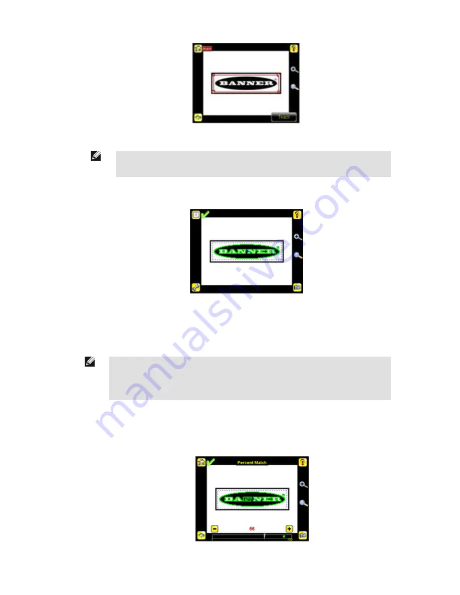
• Adjust the Percent Match parameter. The Percent Match setting adjusts for how closely the inspected part or label matches

the reference part or label. The Percent Match scale is from 0 to 100 where 0 is the most tolerant and 100 is the least tolerant.
Move the slider to the left or to the right.

NOTE: When running a Match inspection with annotations enabled, the sensor will highlight in green
any pattern matches that meet or exceed the value specified for Percent Match. Patterns that are
below the specified value for Percent Match (down to approximately 20%), or out of the Rotation
Range
 (see below), will be colored yellow

1. Using a "bad" part, click the Manual Trigger icon in the lower-right of the screen to capture an image. For this example,

one of the stored images is missing the letter "N," yet the sensor initially sees this as a "good" label.

2. Go to Main Menu > Inspection , and click the Percent Match option.


iVu Series Image Sensor


Rev. E

www.bannerengineering.com - tel: 763-544-3164

51

Содержание iVu Series

Страница 1: ...iVu Series Image Sensor Rev E 1 26 2012 143372...

Страница 2: ...ference 17 3 1 Main Menu Icons 17 3 2 System Menu 17 3 2 1 Sensor Type 18 3 2 2 Sensor Configuration 18 3 2 3 Sensor Information 20 3 2 4 Lock Sensor 21 3 2 5 Motion 21 3 2 6 Discrete I O 21 3 2 7 Dis...

Страница 3: ...w to Debug Using the Emulator from the USB Flash Drive 55 6 iVu Series Updating the Sensor 56 6 1 Update Process 56 6 2 How to Set or Modify a Sensor Name 56 6 3 How to Reset the Sensor Password 57 6...

Страница 4: ...ensor documentation is available in a convenient printable format PDF on the installation CD or on the Banner Web site http www bannerengineering com Banner Website The most current iVu Series sensor...

Страница 5: ...y messages that appeared on your screen A description of what you were doing and what happened A description of how you tried to solve the problem Error Codes see LED Indicator Troubleshooting on page...

Страница 6: ...lian Spanish Japanese Traditional and Simplified Chi nese Easy configuration install connect iVu acquire image set inspection parameters 68 5 mm touch screen LCD display 320 x240 pixels Robust IP67 ho...

Страница 7: ...tened federal regulations that make the quality of pharmaceutical packaging increasingly critical when tablets are inser ted into a blister pack manufacturers need to verify that all the blisters in a...

Страница 8: ...ovide a proper seal on the glass vial If the stopper is missing or incorrectly positioned then the sensor sends a fail output to the line 2 2 Installing the Sensor 2 2 1 Installing and Connecting the...

Страница 9: ...ng it clockwise approximately 5 complete turns or until the Focusing Window disengages from the light lens assembly NOTE The light lens assembly may include an integrated ring light or a blank disk if...

Страница 10: ...are available separately 1 Remove the Lens Enclosure and Lens 2 Install filter behind the retainer ring Make sure it is fully seated 3 Using the provided retainer ring tool thread the retainer ring i...

Страница 11: ...A 11 Black Not used N A 12 Violet Not used N A NOTE Microlens model shown C Mount model connections are identical 2 2 3 Cable Connections for the iVu TG with a Remote Display The cable connections on...

Страница 12: ...Trigger or Remote Teach input on the low to high transition This setting can be changed in the Main Menu System Discrete I O Input Polarity screen on the sensor iVu Low to High Trigger and Remote Tea...

Страница 13: ...g the use of a pull up resistor Option 1 Put a pull up resistor rated approximately 1k ohm between the sensor s positive voltage and the sensor s input as shown below Trigger Input Remote Teach Input...

Страница 14: ...3 Major Features 2 3 1 Demo Mode The first time you power up the iVu TG sensor it starts in Demo Mode Demo Mode uses stored images and inspection parameters that demonstrate how the sensor is set up w...

Страница 15: ...mple scratches on a disc or it can be used to make sure a feature exists on a part Although verifying a feature is present on a part is more commonly an application for an Area sensor a Blemish sensor...

Страница 16: ...nsor Type This displays the Sensor Type menu options 2 Select either Area Blemish or Match 3 Click the Home Screen icon in the upper left corner of the screen to return to the Home screen 2 3 3 Trigge...

Страница 17: ...acteristics of the captured image System icon used to manage the sensor Logs icon used to set up view and save Inspection and System Logs 3 2 System Menu The System menuicon is on the Main Menu and is...

Страница 18: ...the sensor it starts in Demo Mode Demo Mode uses canned images to demonstrate how the sensor operates as a Match Area and Blemish sensor If in Demo Mode Sensor Type will have an option to exit Demo M...

Страница 19: ...Main Menu System Sensor Configuration Load from USB Match Time Limit When the sensor is configured as a Match sensor this screen provides for adjusting the amount of time allotted for the sensor to de...

Страница 20: ...Firmware Version Boot Number Up Timer Hour Count Model Number Sensor Name Main Menu System Sensor Information Click the right arrow next to the Sensor Name field to display a software keyboard that al...

Страница 21: ...ed it must be 4 digits entered using the software keypad If the password is lost use the Password Reset Utility software provided in the CD to obtain a Reset Key NOTE This menu option is not available...

Страница 22: ...condition occurs when a trigger is received while the sensor is busy inspecting the previous image This output signal will be set to active state This signal will be reset upon resetting the History...

Страница 23: ...atched the signal is active until the results of an inspection cause a change in the signal output Main Menu System Sensor Configuration Discrete I O Output 2 3 2 7 Display Settings The Display Settin...

Страница 24: ...een dims after a user selectable period when it is not being used Use the arrow keys or slide the bar at the bottom of the screen to set the LCD screen time out NOTE This screen is not available on th...

Страница 25: ...e a reboot of the sensor NOTE This option is not available on the Emulator Main Menu System Reboot Sensor 3 2 9 Firmware Update The Firmware Update screen is used to load the latest sensor firmware Th...

Страница 26: ...moving the slider to the right allows more light to energize the imager which brightens the image Main Menu Imager Exposure 3 3 3 Gain Gain is an electronic boost to the image signal Increasing Gain...

Страница 27: ...xternal Trigger is selected inspections are triggered in response to an electrical signal on the Trigger input line If Free Run is selected the sensor automatically runs continuous inspections Main Me...

Страница 28: ...Menu Imager Strobe External The External Strobe is a 5V output that can be used for an external light Setting options are Always ON Always OFF or Exposure Based If Exposure Based is selected then the...

Страница 29: ...e The working distance is the distance from the sensor s lens cover to the part being inspected By default the sensor uses the entire FOV in its operation The effective FOV can be reduced in order to...

Страница 30: ...the Main Menu and provides access to parameters that need to be set for an inspection Main Menu Inspection 3 4 1 Match When the sensor is configured as a Match sensor set the ROI Type Percent Match R...

Страница 31: ...bel matches the reference part or label The Percent Match scale is from 0 to 100 where 0 is the most tolerant and 100 is the least tolerant Move the slider to the left or to the right Main Menu Inspec...

Страница 32: ...ail result of the inspection Main Menu Inspection Match Pass Count 3 4 2 Area When configured as an Area sensor the sensor is used to ensure that one or more features of interest are present on a part...

Страница 33: ...use the slider bar at the bottom of the display to fine tune the selection As the slider bar is moved green highlighted areas indicate objects the sensor finds Note that objects that are colored yell...

Страница 34: ...on a disc or it can be used to make sure the a feature exists on a part Although verifying a feature is present on a part is more commonly an application for a sensor config ured as an Area sensor a B...

Страница 35: ...etects edges The Sensitivity scale is from 0 to 100 where 0 means least sensitive and 100 means most sensitive If set near 0 the sensor will only find very sharp edges with strong contrast If set near...

Страница 36: ...colored bar at the bottom of the Pass Count page If within the range brackets the bar is green otherwise it is yellow The brackets can be used to set a tolerance for pass fail Main Menu Inspection Bl...

Страница 37: ...ps account for light varia tions that might affect how well the sensor detects edges on inspected parts The Sensitivity scale is from 0 to 100 where 0 means least sensitive and 100 means most sensitiv...

Страница 38: ...ogs Inspection Logs are stored inspection records that include a captured image the parameters used to inspect it and the results of that inspection Up to ten Inspection Logs can be held in memory on...

Страница 39: ...and Results of the Inspection Use the left and right arrow keys at the bottom of the screen to navigate through the all stored Inspection Logs Setup Use the radio buttons to Disable Logging or to log...

Страница 40: ...E System log will not log changes while in Demo mode Additionally the Emulator does not log changes Main Menu Logs System Logs iVu Series Image Sensor 40 www bannerengineering com tel 763 544 3164 Rev...

Страница 41: ...es good parts and fails bad parts 1 Go to Main Menu Imager Auto Exposure to run the Auto Exposure routine 2 Check the lighting Make sure that the lighting is constant and consistent unchanging over ti...

Страница 42: ...ensor using the clear Focusing Window B 2 Adjust focus while monitoring the focus number To ensure the best image adjust the focus until the Focus Number peaks NOTE Turning the Focusing Window counter...

Страница 43: ...s A Lens B Focusing Window C Locking Clip D Locking Screw E Filter Cap optional F Filter optional NOTE Filter Kits are available separately iVu Series Image Sensor Rev E www bannerengineering com tel...

Страница 44: ...nd will continuously trigger based on a time interval setting This may make it more difficult to make adjustments while setting up the sensor The best practice is as fol lows Go to the Main Menu Image...

Страница 45: ...just the Intensity Range parameter Intensity Range is the range of gray scale values the sensor should look for To set the Intensity Range use the eye dropper on the left of the screen to select the t...

Страница 46: ...ea Range The Area Range is used to set the size limits of a feature of interest Use the slider bar at the bottom of the display to select the range Areas are measured by counting pixels For example a...

Страница 47: ...nce The Demo application shows how the sensor when configured as a Blemish tool can accept or reject parts based on the range of edge pixels the sensor detects in the ROI Start the setup with a good p...

Страница 48: ...ge Length Range The sensor counts all the edge pixels it detects in the ROI The bar at the bottom of the Edge Length Range screen shows all the different contiguous edge segments found Edge segments w...

Страница 49: ...parts and rejects bad 5 To complete the Blemish application setup set triggering as appropriate for your application NOTE Remote Teach does not work with the Blemish Sensor type 4 5 Configuring a Matc...

Страница 50: ...d in the Field of View FOV 1 Teach the sensor a good reference part a Adjust the Region of Interest ROI The ROI is a blue dotted box as shown below b Click Anywhere within the ROI to select it When se...

Страница 51: ...st tolerant Move the slider to the left or to the right NOTE When running a Match inspection with annotations enabled the sensor will highlight in green any pattern matches that meet or exceed the val...

Страница 52: ...option 2 Move the slider at the bottom of the screen to the desired rotation If you are verifying that a label is correctly applied to a container that is on straight you will want to set a small rota...

Страница 53: ...n parameters while the iVu sensor is running Remote Teach is only available when the iVu is configured as a Match sensor The sequence of events for executing a Remote Teach as follows 1 With the senso...

Страница 54: ...rive a On the Main Menu Inspection Logs View Logs screen click the Save icon to save the inspection logs b When prompted select Yes to save sensor configuration along with the Inspection Logs The loca...

Страница 55: ...the Inspection Logs are saved in USB BANNER SENSOR_NAME InspLog and the sensor configuration is saved in USB BANNER SENSOR_NAME For example if the sensor name is myName Configuration File CONFIG CFG p...

Страница 56: ...process Depending on your browser settings you may be asked to confirm or provide a location to save the file Choose to download on yoru desktop Note the file name Double click the file to start extr...

Страница 57: ...Emulator on the PC copy the CONFIG CFG file back to the original folder on the USB drive USB BANNER SENSOR_NAME for example USB BANNER myName NOTE The sensor will look in the original folder for exam...

Страница 58: ...0 will be cropped starting in the upper left 1 Copy the bmp files into the InspLog folder in the iVu Emulator install folder For example copy bmp files into the C Program Files Banner Engineering iVu...

Страница 59: ...and over This indi cates that no inspections are occurring Reboot the sensor The Power LED is lit steady red These type of er rors are reported in the System log and appear highlighted in red Do the...

Страница 60: ...Remote Display Connection 8 pin Euro style M12 female connector accessory cable required for remote display Acquisition 100 fps frames per second max Exposure Time 0 1 ms to 1 049 s Imager 1 3 inch CM...

Страница 61: ...NPN Models Ring Light Options Micro Lens Options C Mount Lens Options 4 3 mm 8 mm 12 mm 16 mm 25 mm None IVURGNX04 IVURGNX08 IVURGNX12 IVURGNX16 IVURGNX25 IVURGNXC Red IVURGNR04 IVURGNR08 IVURGNR12 I...

Страница 62: ...ry to allow its use in personnel safety applications A sensor failure or malfunction can cause either an ener gized or de energized sensor output condition 8 2 Dimensions Micro Lens Dimensions 56 2 2...

Страница 63: ...iVu Series Image Sensor Rev E www bannerengineering com tel 763 544 3164 63...

Страница 64: ...C Mount Lens Dimensions C Mount Lens Covers iVu Series Image Sensor 64 www bannerengineering com tel 763 544 3164 Rev E...

Страница 65: ...SB 19 lock sensor 21 logs inspection 38 system 39 M match parameters percent match 31 51 rotation range 31 52 match sensor 30 Match sensor 18 Match Time Limit 19 maximum pass count 32 34 47 52 menu Di...

Страница 66: ...ear Banner Engineering Corporation will repair or replace free of charge any product of its manufacture found to be defective at the time it is returned to the factory during the warranty period This...

Отзывы: