background image

30

Uso e Manutenzione Avvolgifiocco

Furler’s use and maintenance

Edit. 11.2002

C

ISTRUZIONI DI MONTAGGIO

INSTALLATION


C-11 Consigli per la vela

Se la barca è fornita di numerose vele, ognuna di
queste dovrebbe avere la stessa lunghezza in
inferitura in modo che la testa girevole si trovi alla
stessa altezza quando la vela è completamente issata
per formare tra drizza e strallo un angolo di circa 10
gradi (vedi C-9).

  ATTENZIONE

Quando la vela è armata la testa girevole non
deve mai essere battuta sull'anello di fermo
del terminale. Il carico di trazione che grave-
rebbe sui profili porterebbe alla rottura dei
giunti di collegamento dei profili stessi.

Il migliore modo per avere la stessa lunghezza di
inferitura è aggiungere uno stroppo in Spectra "Y"
di lunghezza opportuna.

Per stabilire questa lunghezza issare la vela portan-
do la testa girevole all’altezza corretta e murare la
vela con uno stroppo di lunghezza adeguata per
poter dare alla vela la normale tensione e rilevarne la
misura "X ".

  AVVERTENZA

La  lunghezza  dello  stroppo  "Y"  deve essere
uguale  alla  lunghezza  "X".

  ATTENZIONE

Posizionare direttamente lo stroppo "Y" sulla
penna della vela; così non sarà rimosso, perduto
o scambiato.

Y

X

44

45

  C-11  Suggestions for the sail

If the boat is supplied with various sails, they should
have all the same hoisting length so that the halyard
swivel is at the same height when the sail is com-
pletely hoisted in order to keep the 10

°

 angle be-

tween halyard and stay (see C-9).

  CAUTION

When the sail is hoisted the halyard swivel has
never to touch the lock ring of the terminal foil.
The load that would then weigh on the foils
would break the splice pieces.

The best way to have the same hoisting length is to
add a Spectra collar “Y” of the right length.

You will find out this length by hoisting the sail and
taking the halyard swivel to the correct height. If you
tack the sail with a collar of an adequate length in
order to give the sail the normal tension you will then
find out the measure “X”.

  CAUTION

The “Y” collar and the “X” collar have to be equal
in length.

  CAUTION

Position the “Y” collar on the sail’s peak, in order
not to remove it or miss it.

Содержание MEJ 1 08-30

Страница 1: ...9 0543 792266 http www bamar it e mail arte bamar it A R TE A R TE Edizione Edition I GB Novembre November 2002 Istruzioni di montaggio Uso e manutenzione Installation Use and maintenance AVVOLGIFIOCCO Magic Electric Jib FORESAIL MAGIC ELECTRIC REEFING and FURLING SYSTEM Mod MEJ 1 08 30 10 40 12 50 14 50 ...

Страница 2: ...ne della cinghia di tasmissione 33 D 2 1 Regolazione della tensione della cinghia 33 D 2 2 Sostituzione del motore elettrico 33 D 3 Ingrassaggio 34 D 4 Inconvenienti cause rimedi 35 E PARTI DI RICAMBIO E 1 Parti di ricambio riduttore 36 E 2 Parti di ricambio profili 38 GARANZIA 39 A GENERAL INFORMATION Introduction 3 A 1 Symbols to be found in this manual 4 A 2 Basic tools 5 A 3 Description of the...

Страница 3: ...tem You have to read and understand this manual before using the furler and carrying out any operation on it Thismanualhasbeendividedintosections chapters and paragraphs in order to present the information in a structured and clear way The pages are numbered progressively The search for information may be done either throughthekeywordsusedastitlesforthesections or through the consultation of the g...

Страница 4: ... la sicurezza personale né il buon funzionamen to della macchina RISPETTA L AMBIENTE Per attirare l attenzione verso importanti informazioni per il rispetto dell ambiente INFORMAZIONI GENERALI GENERAL INFORMATION A A 1 SYMBOLSTOBEFOUNDINTHISMANUAL This manual uses five types of graphic safety symbols which highlight as many danger or information levels DANGER It draws your attention to situations ...

Страница 5: ...con strallo a terra ed alcune informazio ni per il montaggio con strallo armato A 4 Imballo Gli avvolgifiocco elettrici vengono forniti completi degli accessori per il montaggio in due robuste scatole sovrapponibili di peso e dimensioni varia bili in funzione del modello e della lunghezza richie sta INFORMAZIONI GENERALI GENERAL INFORMATION A CAUTION Avoid starting to assemble the furler without t...

Страница 6: ...orrimento Q b 8 Tubetto grasso 1 9 Liquido frenafiletti 1 10 Testa girevole gambetti 1 11 Viti per fissaggio giunti chiave esagonale Q b 12 Bozzello guidadrizza con rivetti 1 13 Boccola di adattamento profilo 1 14 Libretto istruzioni 1 INFORMAZIONI GENERALI GENERAL INFORMATION A A 5 Receipt of goods The goods are shipped at the receiver s own risk Thepurchaserwillhavetocheckthegoodscarefully and s...

Страница 7: ... B C Ref 08 30 10 40 12 50 14 50 ø r 7 8 8 10 12 14 Max vela m2 45 70 80 90 LFT max m 10 12 14 5 15 5 øL mm 13 23 30 30 A 104 110 115 115 B 168 185 190 190 ø C 52 52 52 52 D 88 93 100 100 E 120 180 180 180 F 1300 1300 1300 1300 G 910 910 910 910 H 500 500 500 500 I 460 460 460 460 J 4 0 4 0 5 0 8 0 L 52 47 42 42 M 65 65 65 65 N 130 130 130 130 O 260 260 260 260 P 375 375 375 375 Q 420 420 420 420 ...

Страница 8: ... 0 15 0 19 0 31 L inc 2 04 1 85 1 65 1 65 M inc 2 55 2 55 2 55 2 55 N inc 5 11 5 11 5 11 5 11 O inc 9 44 9 44 9 44 9 44 P inc 14 76 14 76 14 76 14 76 Q inc 16 53 16 53 16 53 16 53 R inc 18 30 18 30 18 30 18 30 U inc 1 77 1 77 1 77 2 55 V inc 1 18 1 57 1 96 1 96 W inc 31 88 31 88 31 88 31 88 X inc 29 52 29 52 29 52 29 52 Y inc 2 36 2 36 2 36 2 36 Z inc 0 78 1 18 0 98 0 98 a inc 1 77 1 77 1 77 1 77 ...

Страница 9: ...del lavoro INFORMAZIONI GENERALI GENERAL INFORMATION A A 7 Identification data Type and model Electric foresail furler type MEJ1 Model 08 30 10 40 12 50 14 50 Manufacturer A R TE srl Via Talete 2 a int 3 47100 Forlì Italy Identification plate The furler s identification plate is applied on the motorization A 8 Proper use The electric foresail furling system is to be used for furling and reefing th...

Страница 10: ... saranno integrate nei capi toli seguenti da specifiche avvertenze ogni qualvolta dovesse risultare necessario Nonostante l estrema semplicità delle operazioni di montaggio e la facilità nell uso dell attrezzatura è opportuno che vengano rispettate alcune elementari norme di sicurezza Queste norme garantiranno oltre all incolumitàfisicadell operatore uncorrettousodel prodotto ed una sua ottimale r...

Страница 11: ...iversamente con terminali più ingombranti verificare che le dimensioni del termi nale non siano superiori a quelle del diametro inter no dei profili vedi A 6 pag 7 In questo caso sarà necessario eliminare il terminale e ripiombare dopo il montaggio dei profili con un terminale rapido tipo Stalok vedi C 1 3 ISTRUZIONI DI MONTAGGIO INSTALLATION C C 1 Preliminary operations Open all boxes and check t...

Страница 12: ...per strallo Asta filettata lunga con attacco rapido STALOK Asta filettata corta con attacco rapido STALOK TerminaleadocchioconattaccorapidoSTALOK Snodo ricavato da barra Perno speciale C 1 3 Stay accessories optional Terminals and special accessories which make the installation easier Toggle turnbuckle with threaded stud Long threaded stud with STALOK rapid connection SHORT threaded stud with STAL...

Страница 13: ...are all interno il tenditore previa verifica degli ingombri del tenditore C ISTRUZIONI DI MONTAGGIO INSTALLATION Perno speciale snodo Perno speciale snodo Perno speciale snodo Special clevis pin bar toggle Special clevis pin bar toggle Special clevis pin bar toggle C 1 4 Chain plate The furler s motorization has to be connected to the chain plate by means of a special clevis pin the pin diameter h...

Страница 14: ...n ottavo profilo alla lunghezza di 780 mm Vedere il capitolo C 3 Preparazione al montaggio per la corretta procedura per il taglio del profilo C ISTRUZIONI DI MONTAGGIO INSTALLATION C 2 Determining quantity and length of foils In order to determine the number of foils needed you must proceed as follows after having defined the connection on the drum s link plates Check the stay length A from the c...

Страница 15: ...use and maintenance X Y Z W A C ISTRUZIONI DI MONTAGGIO INSTALLATION Ref 08 30 10 40 12 50 14 50 W1 810 810 810 810 W2 755 755 755 755 W3 710 710 710 710 A W X Z 50 Numero dei profili 1500 Number of foils X 750 mm Z 370 mm Misura fissa Fixed measures W1 W3 W2 ...

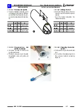
Страница 16: ...l foro precedentemente esegui to Con una lima a taglio dolce sbavare le estremità del profilo con particolare cura le sedi del gratile ø 7 C ISTRUZIONI DI MONTAGGIO INSTALLATION 3 1 2 4 5 C 3 How to prepare the foils C 3 1 Cutting the foil to measure Mark out on a foil the measure you derived from the formula on page 14 Drill the foil with a ø 7 mm drill Cut the foil with a hand saw on thecentreof...

Страница 17: ...ofilo terminale Montare l anello di fermo sul profilo terminale Mettere una goccia di liquido frenafiletti sulle viti prima di serrarle 7 8 C B A 6 C ISTRUZIONI DI MONTAGGIO INSTALLATION C 3 2 Drilling the foil Drill and thread the foil for the screws used to hold the splice pieces See the table hereafter for measurements A B C 08 30 15 25 ø4 25 M5 10 40 20 30 ø5 M6 12 14 50 25 40 ø6 75 M8 C 3 3 P...

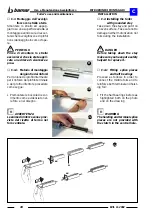
Страница 18: ...ole di scor rimento come evidenziato nel le foto e nel disegno AVVERTENZA Leanimedirinforzosonosprov viste del rivetto di fermo nel foro centrale 180 90 A 9 10 11 12 C ISTRUZIONI DI MONTAGGIO INSTALLATION C 4 Installing the furler with grounded stay Take down the stay and put it on an even surface Take care not to damage neither motorization nor foils during the installation DANGER Before taking d...

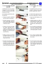
Страница 19: ...con le tacche previste sull anima Mettere una goccia di liquido frenafiletti quindi fissare l ani ma con le viti e la chiave esagonale fornita 13 14 15 16 C ISTRUZIONI DI MONTAGGIO INSTALLATION C 4 2 Fitting the terminal foil You will have to apply a splice piece without clutch on the ter minal foil How to fit the splice piece to the terminal foil Insert the half bearings in the aluminium piece No...

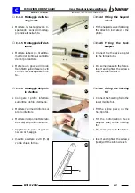
Страница 20: ... fissare l ani ma con le viti e la chiave esagonale fornita Montare tutti i profili necessari avendo cura di montare come penultimo il profilo preceden tementetagliatoamisuraquin di perultimo ilprofiloinferitore 17 18 19 20 21 22 23 C 4 3 Fitting the middle foils The middle foils have to be con nected by means of the splice pieces supplied with clutch In order to fit the splice pieces be tween two...

Страница 21: ...anima di rinforzo sul profilo inferitore Montare il corpo riduttore lato boccola sul profilo inferitore Applicare un poco di grasso nei fori di fissaggio Inserire e serrare le viti rif 4 con la chiave fornita 4 24 25 26 27 29 C 4 4 Fitting the halyard swivel Fit the halyard swivel following the direction indicated in the photo C 4 5 Fitting the tack adapter Connect the the tack adapter to the torq...

Страница 22: ...careiltenditore avendo cura di non accorciar lo oltre la lunghezza originaria Abbassare il riduttore fino a fissare i 3 grani nella posizione originale 4 30 31 C ISTRUZIONI DI MONTAGGIO INSTALLATION C 5 How to install the furler on board Connect the top of the stay to the mast head using a halyard DANGER Do not attempt to install the assembled system in strong winds CAUTION Make sure not to over b...

Страница 23: ...llamanovelladiemergenzail corpodelriduttoredeveessere montato come illustrato nella figura a lato Diversamente il riduttore può essere ruotato di 90 180 270 C 7 How to install the motorization on the link plates Prepare the link plates to be fitted to the motorization depending on the kind of installation chosen see pictures on page 13 IfthestickersBarenotattached on the four sides of the motoriza...

Страница 24: ... di pen na Mettere in tiro la drizza e sollevarla ripetutamente man mano che i profili vengono assemblati Al termine del montaggio recuperare la testa gi revole ammainandola C 8 How to install the furler on armed mast You do not have to take the stay off to carry out the installation it is enough to disconnect it from the chain plate If you choose this solution the extru sions will not go through ...

Страница 25: ...ifiocco è completato ATTENZIONE E molto importante che nelle fasi di avvolgimento e svol gimento dell avvolgifiocco lo strallo di prua sia ben tesato Quando necessario regolar ne la tensione unitamente a quella dello strallo di pop pa 350 mm 10 C ISTRUZIONI DI MONTAGGIO INSTALLATION C 9 Fitting the halyard swinging block Installthehalyardswingingblock byfollowingtheinstructionshere after WARNING T...

Страница 26: ... siacompatibileconicomponentidell avvolgifiocco Qui di seguito viene rappresentato uno schema preferenziale ma non limitativo di applicazione e posizionamento dei componenti 37 C 10 Electric connection Procede with the connection of the electric wiring after having installed the furler WARNING The electric wiring has to be carried out by skilled personnel Please make sure the the voltage of the bo...

Страница 27: ...Cavo alimentazione ACB marrone 1 5 mm2 ACB electric cable brown 1 5 mm2 Cavo abilitazione teleinvertitore blu 1 5 mm2 Electric cable abilitating the solenoid blue 1 5 mm2 Cavo per segnalazione acustica e visiva Electric cable for light and sound signal chiedere le specifiche alla casa produttrice ask the manufacturer for specifications Cavo alimentazione ACB vedi tabella 10 2 ACB electric cable se...

Страница 28: ... E possibile azionare l avvolgifiocco per mezzo di un radiocomando Per l installazione utilizzare gli schemi di montag gio e le istruzioni fornite dal costruttore Si consiglia comunque di applicare il radiocomando in abbinamento all impianto convenzionale C 10 3 Electronic overload cut out ACB The electric furler has an electronic overload cut out named ACB which is is pre calibrated by our techni...

Страница 29: ...o dei comandi dell avvolgifiocco Possibili soluzioni di azionamenti manuali 41 Con manovella winch 42 Con manovella snodata 43 Con inserto per trapano a batteria C ISTRUZIONI DI MONTAGGIO INSTALLATION C 10 5 Manual emergency In case of electric failure the electric furler may be manually operated Take off the protection cap Insert the handle Rotate the handle either clockwise or anti clockwise in ...

Страница 30: ...ione e rilevarne la misura X AVVERTENZA La lunghezza dello stroppo Y deve essere uguale alla lunghezza X ATTENZIONE Posizionare direttamente lo stroppo Y sulla penna della vela così non sarà rimosso perduto o scambiato Y X 44 45 C 11 Suggestions for the sail If the boat is supplied with various sails they should have all the same hoisting length so that the halyard swivel is at the same height whe...

Страница 31: ... che la testa girevole non vada ol tre i profili si consiglia una distanza di 5 10 cm tra il lato superiore della testa girevole e l anello di fermo del profilo terminale C 12 How to hoist the sail In order to hoist the sail you will have to Attach the halyard onto the shackle located on the top of the halyard swivel Attach the head of the sail to the shackle located on the bottom of the halyard s...

Страница 32: ...are i cristalli di sale depositati sulla sua superficie particolare cura va dedicata al lavaggio della sezione inferiore che comprende il riduttore e la testa girevole Proteggere con specifici prodotti lubrificanti l avvolgifiocco con particolare riferimento alle parti soggettearotazionee oscorrimento corporiduttore testa girevole e avvolgerle con un robusto foglio di nailon o tela incerata D MANU...

Страница 33: ...i Smontare il tappo di protezione Smontare le tre viti di fissaggio del coperchio lato trasmissione Far leva sotto il coperchio con una spatola sottile per facilitare l estrazione Allentarelavitedifissaggiodelgaloppinotendicinghia D 2 How to change the drive belt DANGER Before carrying out any kind of maintenance cut the electric supply and prevent anyone from using the furler s commands If you ha...

Страница 34: ...che gli ingranaggi siano coperti di lubrificante Qualora sia necessario provvedere al reintegro di gras so con una spatola fino a coprire completamente gli in granaggi Si consiglia l uso di grasso minerale Shell Super Greases GBX densità 00 D MANUTENZIONE MAINTENANCE Take off the the belt Take off the the sheave which tensions the drive belt Take off the lower sheave helping yourself with a double...

Страница 35: ...ui da drizza sia correttamente in stallato vedi pag 25 Regolare la posizione della te sta girevole vedi pag 30 31 Verificare la scotta Regolareiltrimmernellascato la elettronica ACB vedi pag 28 D MANUTENZIONE MAINTENANCE Problem The system does not rotate The electric furler turns and then stops Cause Halyard wrapped around the foils Halyard swivel badly adjusted Lack of electricity Halyard wrappe...

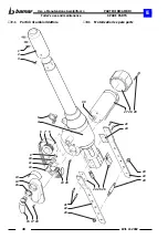
Страница 36: ...urler s use and maintenance Edit 11 2002 E 1 Parti di ricambio riduttore E PARTI DI RICAMBIO SPARE PARTS E 1 Motorization s spare parts M E J 1 1 2 3 4 5 21 24 23 22 23 21 22 23 16 17 18 19 20 6 7 8 9 10 11 12 13 14 15 24 25 26 27 28 29 30 ...

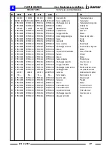
Страница 37: ... drive side 15 ZMEJ012 08 ZMEJ012 10 ZMEJ012 12 ZMEJ012 14 Paraolio Oil seal 16 ZMEJ013 08 ZMEJ013 10 ZMEJ013 12 ZMEJ013 14 Adesivo Sticker 17 ZMEJ014 08 ZMEJ014 10 ZMEJ014 12 ZMEJ014 14 Tappo emergenza Emergency cap 18 ZMEJ015 08 ZMEJ015 10 ZMEJ015 12 ZMEJ015 14 Vite fissaggio coperchio Cover lock screw 19 ZMEJ016 08 ZMEJ016 10 ZMEJ016 12 ZMEJ016 14 Puleggia conduttrice Drive sheave 20 ZMEJ017 08...

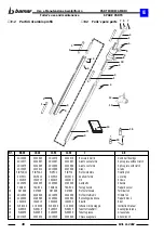
Страница 38: ...013 2X15013 Anello di fermo Lock ring 7 1X22015 1X22015 1X22015 1X22015 Viti Screws 8 2C25050 2C25055 2C25060 2C25060 Gambetto Shackle 9 TSGRC1 TSGRC2 TSGRC4 TSGRC4 Testa girevole Halyard swivel 10 O27998 O37998 O47998 O47998 Profilo terminale Terminal foil 11 2D14030 2D14040 2D14050 2D14050 Profilo intermedio Middle foil 12 2C26060 2C26060 2C26062 2C26062 Bozzello guida drizza Halyard block 13 1X...

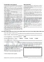
Страница 39: ... in nessun caso il periodo di garanzia stabilito Sono escluse dalla garanzia le parti non costruite direttamente tubi pompe distributori ecc per le quali valgono le stesse garanzie delle Case Costruttrici La garanzia diviene operante soltanto al ricevimento della presente scheda compilata in ogni sua parte MEJ1 A R TE srl garantisce il beneficio dell esten sione della garanzia sull avvolgifiocco a...

Страница 40: ...ia corretto con il terminale dello strallo ATTENZIONE La garanzia non copre i danni causati da un sistema che non sia stato installato corretta mente danneggiato da una collisione o utilizza to impropriamente After the installation the client must check that The sail luff is cut to the correct length The locking devices attaching motorization are properly installed All screws are tightened The hal...

Страница 41: ...41 Edit 11 2002 Uso e Manutenzione Avvolgifiocco Furler s use and maintenance NOTE NOTE ...

Страница 42: ...42 Uso e Manutenzione Avvolgifiocco Furler s use and maintenance Edit 11 2002 NOTE NOTE ...

Страница 43: ...43 Edit 11 2002 Uso e Manutenzione Avvolgifiocco Furler s use and maintenance NOTE NOTE ...

Страница 44: ...egnativo Technical data and figures are only for information and not binding Advanced Research and Technology srl Via Talete 2 A int 3 47100 FORLI ITALIA Phone 39 0543 798670 Fax 39 0543 792266 http www bamar it e mail arte bamar it A R TE A R TE VEGA Forlì Cod 3 10 030 0 ...

Отзывы: