


When the burner is ignited at the minimum flow-rate, if the modulation
probe allows it (adjusted to a temperature or pressure which is greater
than that present in the boiler) the air/gas adjustment servomotors
activate,
•
in a clockwise direction the air flow increases;
•
anticlockwise rotation: the air flow decreases.
Thus gradually increasing gas supply and combustion air until the
maximum supply level set for the burner is reached.
•
in a clockwise direction the air flow increases;
•
anticlockwise rotation: the air flow decreases.
causing a gradual increase in the combustion air and fuel flow, until it
reaches the maximum flow setting of the burner.
The burner remains in the maximum flow position until the temperature
or pressure is high enough to trip the modulation probe, which reverses
the rotation of the air adjustment servomotor.
Gas and air flow increase or decrease occurs at short time intervals.
With this procedure, the modulation system attempts to balance
the amount of heat supplied to the boiler with respect to the system
requirement.
The modulation probe installed on the boiler measures any request
variation and automatically adjusts fuel and combustion air supply, by
starting the air/gas adjustment servomotor and increasing or reducing
rotation as necessary.
Flame presence is detected by the dedicated control device (UV
photocell).
If the threshold value (temperature or pressure), to which the complete
shut-down device (thermostat or pressure switch) is set, is reached
even with minimum gas and air output, the burner will be shut down
when the device is triggered.
When temperature or pressure returns below the shut-down device
tripping value, the burner is activated once again according to the
program described in the previous section.
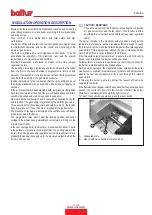
DETAIL OF THROTTLE VALVE FOR GAS FLOW REGULATION
BY MEANS OF SERVOMOTOR
A
B
A) Butterfly gas valve position reference index
B) Gas modulation servo motor
18 / 34
0006081328_202202
ENGLISH
Содержание 17530020
Страница 2: ......
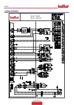
Страница 32: ...SCHEMI ELETTRICI TBG 80 360LX ME TBG 80 360 ME 30 34 0006081328_202202 ITALIANO...
Страница 33: ...TBG 80 360LX ME TBG 80 360 ME 31 34 0006081328_202202 ITALIANO...
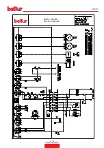
Страница 34: ...TBG 80 360LX ME TBG 80 360 ME I1 I2 BA I4 I3 32 34 0006081328_202202 ITALIANO...
Страница 36: ...34 34 0006081328_202202 ITALIANO...
Страница 66: ...WIRING DIAGRAMS TBG 80 360LX ME TBG 80 360 ME 30 34 0006081328_202202 ENGLISH...
Страница 67: ...TBG 80 360LX ME TBG 80 360 ME 31 34 0006081328_202202 ENGLISH...
Страница 68: ...TBG 80 360LX ME TBG 80 360 ME I1 I2 BA I4 I3 32 34 0006081328_202202 ENGLISH...
Страница 70: ...34 34 0006081328_202202 ENGLISH...
Страница 71: ......


