background image

• 

If there is any fault or if the equipment is not working properly, de-

activate the equipment and do not attempt to repair it or tamper with 

it directly. Contact only qualified personnel.

• 

Any product repairs must only be carried out by BALTUR authorised 

assistance centres or by its local distributor using only original spare 

parts.

• 

The manufacturer and/or its local distributor are not liable for any 

accident or damage caused by unauthorised changes of the product 

and by failure to follow the rules described in the manual.

SAFETY WARNINGS FOR INSTALLATION

• 

The equipment must be installed in a well-ventilated suitable room in 

compliance with the laws and regulations in force.

•  Ventilation grille section and installation room aeration openings 

must not be obstructed or reduced.

• 

The installation room must NOT have the risk of explosion and/or 

fire.

• 

Before installing the equipment we recommend to carefully clean the 

interior area of all fuel supply system pipes.

• 

Before connecting the equipment check that the details on the plate 

correspond to those of the utility supplies (electricity, gas, light oil or 

other fuel).

• 

Make sure the burner is firmly fixed to heat generator according to 

manufacturer instructions.

•  Connect to the source of energy according to state-of-the-art 

standards  as  described  in  the  explanatory  diagrams  and  in 

compliance with the regulatory and law requirements in force at the 

moment of installation.

• 

Check that the fume disposal system is NOT obstructed.

• 

If  it  is  decided  not  to  use  the  burner  any  more,  the  following 

procedures must be performed by qualified technicians:

 -

Switch off the electrical supply by disconnecting the power cable 

from the main switch.

 - Cut off the fuel supply using the shut-off valve and remove the 

control wheels from their position.

 - Render harmless any potentially dangerous parts.

WARNINGS FOR START UP, TEST, USE AND MAINTENANCE

• 

Start up, test and maintenance of the equipment must only be carried 

out by qualified technicians, in compliance with current regulations.

• 

Once the burner is fixed to the heat generator, make sure that the 

generated flame does not come out of any slot during testing.

•  Check equipment fuel supply pipe seal.

• 

Check that fuel flow rate equals the power required to the burner.

• 

Set  the  burner  fuel  capacity  to  the  power  required  by  the  heat 

generator.

• 

Fuel  supply  pressure  must  be  within  the  values  indicated  on  the 

plate on the burner and/or manual

• 

The fuel supply system is suitably sized for the flow required by the 

burner and that it has all the safety and control devices required by 

current standards.

• 

Check that all terminals on the power supply conductors are properly 

tightened.

• 

Before starting up the burner, and at least once a year, have qualified 

technicians perform the following operations:

 -

Set the burner fuel capacity to the power required by the heat 

generator.

 -

Check combustion and adjust combustion air and fuel flow and ( 

O2 / CO / NOx) emissions in accordance with the law in force.

 -

Check the adjustment and safety devices are working properly.

 -

Check the efficiency of the combustion products exhaust duct.

 -

Check seal in the fuel supply pipe internal and external section.

 -

At the end of the adjustment procedures, check that all the 

locking devices of mechanical securing systems are properly 

tightened.

 -

Make sure that the use and maintenance manual of the burner is 

available.

• 

If  the  burner  repeatedly  stops  in  lock-out,  do  not  keep  trying  to 

manually reset it but call a qualified technician.

• 

If you decide not to use the burner for a while, close the valve or 

valves that supply the fuel.

3 / 34

0006081328_202202

ENGLISH

Содержание 17530020

Страница 1: ...NERS ITALIANO Manuale istruzioni per l installazione l uso e la manutenzione IT Instruction manual for installation use and maintenance EN TBG 80 LX ME TBG 110 LX ME TBG 140 LX ME TBG 200 LX ME TBG 26...

Страница 2: ......

Страница 3: ...limentazione 14 Schema di principio rampa gas 14 Collegamenti elettrici 15 Descrizione del funzionamento a modulazione 17 Accensione e regolazione 19 Misurazione della corrente di ionizzazione 20 Sens...

Страница 4: ...l bruciatore NON deve essere utilizzato in cicli produttivi e processi industriali disciplinati questi ultimi dallo Standard EN 746 2 Contattare gli uffici commerciali Baltur La data di produzione del...

Страница 5: ...rebbero essere potenziali fonti di pericolo AVVERTENZE PER L AVVIAMENTO IL COLLAUDO L USO E LA MANUTENZIONE L avviamento il collaudo e la manutenzione devono essere effettuati esclusivamente da person...

Страница 6: ...ertura dei contatti uguale o superiore a 3 mm per l allacciamento alla rete elettrica come previsto dalle normative di sicurezza vigenti condizione della categoria di sovratensione III Sguainare l iso...

Страница 7: ...ivo pu essere abilitata la funzionalit di ripristino automatico rimuovendo in modo irreversibile il relativo talloncino in plastica sul dispositivo termico posto a protezione del motore ventola Nel co...

Страница 8: ...ONIZZAZIONE SONDA IONIZZAZIONE Apparecchiatura BT 320 BT 320 BT 320 BT 320 Regolazione portata aria CAMMA ELETTRONICA CAMMA ELETTRONICA CAMMA ELETTRONICA CAMMA ELETTRONICA Temperatura aria ambiente di...

Страница 9: ...portata aria CAMMA ELETTRONICA CAMMA ELETTRONICA Temperatura aria ambiente di funzionamento C 15 40 15 40 Pressione sonora dBA 89 82 Potenza sonora dBA 95 Peso con imballo kg 110 117 3 Peso senza imb...

Страница 10: ...eri di certificato di omologazione 14 Data di produzione mese anno 15 Codice a barre matricola bruciatore DATI REGISTRAZIONE PRIMA ACCENSIONE Modello Data ora Tipo di gas Indice di Wobbe inferiore Pot...

Страница 11: ...uti su caldaie di prova rispondenti alla norma EN676 e sono orientativi per gli accoppiamenti bruciatore caldaia Per il corretto funzionamento del bruciatore le dimensioni della camera di combustione...

Страница 12: ...uadro elettrico 8 Motore 9 Servomotore regolazione aria 10 Servomotore regolazione gas 11 Targa identificazione bruciatore 0002471121nom 9 7 8 1 2 3 4 5 6 10 6 1 11 QUADRO ELETTRICO 1 Apparecchiatura...

Страница 13: ...0 160 200 1315 200 450 240 219 TBG 200 LX ME 610 240 370 540 380 160 200 1315 200 450 250 219 TBG 260 LX ME 700 280 420 560 400 160 200 1320 200 450 250 219 TBG 360 LX ME 820 400 420 590 390 160 235 1...

Страница 14: ...ni CO metano propano 100 mg kWh CARATTERISTICHE TECNICO FUNZIONALI Funzionamento a due stadi progressivi o modulante Possibilit di funzionamento a modulazione di potenza tramite montaggio sul quadro d...

Страница 15: ...rmazione del locale caldaia e alla posizione di ingresso della tubazione gas PERICOLO ATTENZIONE Con valvola di dimensioni notevoli esempio DN65 oppure DN80 prevedere un adeguato supporto per evitare...

Страница 16: ...M 12 10 9 14 11 13 8 4 7 6 5 3 2 1 0002910950N2 A CURA DELL INSTALLATORE RAMPA GAS FORNITA DAL COSTRUTTORE 1 Valvola di intercettazione manuale 2 Giunto antivibrante 3 Filtro gas 4 Pressostato di min...

Страница 17: ...stati vedere il relativo schema elettrico Sguainare l isolante esterno del cavo di alimentazione nella misura strettamente necessaria al collegamento evitando cos che il filo possa venire a contatto c...

Страница 18: ...ttrico del bruciatore consentita esclusivamente a personale professionalmente qualificato In caso di reti elettriche a 230 V fase fase se queste sono sbilanciate la tensione fra elettrodo di rilevazio...

Страница 19: ...ell erogazione aria gas che si portano al punto minimo 200 Se il termostato o pressostato di caldaia di 2 stadio lo consente regolato ad un valore di temperatura o pressione superiore a quella esisten...

Страница 20: ...to o la diminuzione dell erogazione aria e gas avviene a brevi intervalli di tempo Con questa manovra il sistema di modulazione cerca di equilibrare la quantit di calore fornito alla caldaia con quant...

Страница 21: ...corretto se necessario scambiare il posto ai due cavi della linea che alimenta il motore per invertire il senso di rotazione Inserire ora l interruttore generale L apparecchiatura di comando riceve c...

Страница 22: ...la fotocellula dalla sede l apparecchiatura si deve portare immediatamente in blocco verificare l efficienza dei termostati o pressostati di caldaia l intervento deve arrestare il bruciatore verificar...

Страница 23: ...ruciatore lavora alla massima potenza richiesta dall impianto Correggere la posizione del dispositivo chiusura aria della testa di combustione spostandolo in avanti o indietro in modo da avere un flus...

Страница 24: ...MC TBG 260 LX ME TBG 360 LX ME TBG 80 LX P LX PN V TBG 80 LX ME LX MC A A A B B B 1 1 1 1 1 1 2 2 2 2 2 2 3 3 3 4 4 4 5 5 5 C A B C TBG 80 LX ME 5 8 TBG 110 LX ME 5 5 TBG 140 LX ME 5 5 TBG 200 LX ME 5...

Страница 25: ...ne e o dalla combustione Fare attenzione durante le operazioni di rimontaggio di centrare esattamente la testa di uscita gas rispetto agli elettrodi per evitare che gli stessi si trovino a massa con c...

Страница 26: ...scritto dopo aver verificato la corretta posizione degli elettrodi di accensione e di ionizzazione CAUTELA AVVERTENZE All atto della chiusura del bruciatore tirare delicatamente verso il quadro elettr...

Страница 27: ...O PATTINO E VITI ANNO LEVE TIRANTI SNODI SFERICI CONTROLLO EVENTUALI USURE LUBRIFICAZIONE COMPONENTI ANNO IMPIANTO ELETTRICO VERIFICA CONNESSIONI E SERRAGGIO MORSETTI ANNO INVERTER PULIZIA VENTOLA DI...

Страница 28: ...a o di pagamento sono indipendenti e non fanno riferimento alla vita attesa di seguito indicata Per condizioni operative normali si intendono applicazioni su caldaie ad acqua e generatori di vapore op...

Страница 29: ...gassificazione naturale da batteria di bombole o serbatoio utilizzabile solo per impianti di piccola potenza La capacit di erogazione in fase di gas in funzione delle dimensioni del serbatoio e della...

Страница 30: ...duttore di 2 salto Uscita 30 hPa mbar Portata il doppio del massimo richiesto dall utilizzatore Filtro a Y Filtro Filtro Presa di pressione Riduttore di 2 salto Uscita Pressione minima alimentazione r...

Страница 31: ...fogata dall aria caso di prima accensione La pressione del gas insufficiente o eccessiva Passaggio aria tra disco e testa troppo chiuso RIMEDIO Invertire l alimentazione lato 230V del trasformatore di...

Страница 32: ...SCHEMI ELETTRICI TBG 80 360LX ME TBG 80 360 ME 30 34 0006081328_202202 ITALIANO...

Страница 33: ...TBG 80 360LX ME TBG 80 360 ME 31 34 0006081328_202202 ITALIANO...

Страница 34: ...TBG 80 360LX ME TBG 80 360 ME I1 I2 BA I4 I3 32 34 0006081328_202202 ITALIANO...

Страница 35: ...VENTOLA MV MOTORE VENTOLA N1 REGOLATORE ELETTRONICO P M PRESSOSTATO DI MASSIMA P1 CONTAORE PA PRESSOSTATO ARIA Pm PRESSOSTATO DI MINIMA S1 INTERRUTTORE MARCIAARRESTO S2 PULSANTE SBLOCCO SG1 2 SEZIONA...

Страница 36: ...34 34 0006081328_202202 ITALIANO...

Страница 37: ...ne 14 Gas train block diagram 14 Electrical connections 15 Modulation operation description 17 Starting up and regulation 19 Ionisation current measurement 20 Flame sensor 20 Air regulation on the com...

Страница 38: ...ch as building heating and domestic hot water production The burner must NOT be used in production cycles and industrial processes the latter governed by the Standard EN 746 2 Contact sales offices Ba...

Страница 39: ...el supply using the shut off valve and remove the control wheels from their position Render harmless any potentially dangerous parts WARNINGS FOR START UP TEST USE AND MAINTENANCE Start up test and ma...

Страница 40: ...ce with current safety regulations condition of overvoltage category III is required Remove the external insulating seal of the supply pipe necessary for the connection preventing the cable to touch m...

Страница 41: ...of protection devices The automatic reset function on the thermal device which protects the fan motor cannot be enabled by irreversibly removing the relevant plastic label for any reason As for the co...

Страница 42: ...OBE IONISATION PROBE IONISATION PROBE Control box BT 320 BT 320 BT 320 BT 320 Air flow rate regulation ELECTRONIC CAM ELECTRONIC CAM ELECTRONIC CAM ELECTRONIC CAM Operating ambient air temperature C 1...

Страница 43: ...BT 320 Air flow rate regulation ELECTRONIC CAM ELECTRONIC CAM Operating ambient air temperature C 15 40 15 40 Sound pressure dBA 89 82 Sound power dBA 95 Weight with packaging kg 110 117 3 Weight with...

Страница 44: ...ate of approval 14 Manufacturing date month year 15 Bar code serial number of burner DATA RECORDED DURING FIRST START UP Model Date Time Type of gas Lower Wobbe index Lower calorific power Min gas flo...

Страница 45: ...T The operating ranges are obtained from test boilers corresponding to Standard EN676 and are indicative of the burner boiler combination For correct working of the burner the size of the combustion c...

Страница 46: ...ME 7 Electrical panel 8 Motor 9 Air regulation servomotor 10 Gas regulation servomotor 11 Burner identification plate 0002471121nom 9 7 8 1 2 3 4 5 6 10 6 1 11 ELECTRICAL PANEL 1 Control box 2 Air pre...

Страница 47: ...160 200 1315 200 450 240 219 TBG 200 LX ME 610 240 370 540 380 160 200 1315 200 450 250 219 TBG 260 LX ME 700 280 420 560 400 160 200 1320 200 450 250 219 TBG 360 LX ME 820 400 420 590 390 160 235 13...

Страница 48: ...3 80 4 60 Propane natural gas CO emissions 100 mg kWh TECHNICAL FUNCTIONAL CHARACTERISTICS Operation at two progressive stages modulating Ability to operate with output modulation by means of automat...

Страница 49: ...the set up of the boiler room and the position in which the gas pipeline arrives DANGER ATTENTION In case of very large valves e g DN65 or DN80 make sure there is a suitable support to prevent excess...

Страница 50: ...11 13 8 4 7 6 5 3 2 1 0002910950N2 TO BE CARRIED OUT BY THE INSTALLER GAS TRAIN SUPPLIED BY THE MANUFACTURER 1 Manual shut off valve 2 Vibration proof joint 3 Gas filter 4 Minimum gas pressure switch...

Страница 51: ...electrical connections line and thermostats Strip the outer insulation of the power cable just as necessary for the connection preventing the cable to touch metal parts and provide a longer length fo...

Страница 52: ...nly professionally qualified personnel may open the burner electrical switchboard In case of phase phase 230V electrical grids if these latter are unbalanced the voltage between flame detection electr...

Страница 53: ...ast the locking position and sends voltage to the air gas supply adjustment servomotors which go to the minimum point 200 If the second stage boiler thermostat or pressure switch allow it set to a tem...

Страница 54: ...se occurs at short time intervals With this procedure the modulation system attempts to balance the amount of heat supplied to the boiler with respect to the system requirement The modulation probe in...

Страница 55: ...exchange the position of the two cables in the line that feeds the motor in order to reverse the direction of revolution Now switch on the main switch This powers on the control device and the program...

Страница 56: ...rom its seat the apparatus should shut down immediately check the efficiency of the thermostats or boiler pressure switches they should shut down the burner when triggered check the efficiency of the...

Страница 57: ...capacity required by the system Correct the position of the device that closes the air of the combustion head moving it forward or backward in order to obtain an air flow suitable for the supply with...

Страница 58: ...ME LX MC TBG 260 LX ME TBG 360 LX ME TBG 80 LX P LX PN V TBG 80 LX ME LX MC A A A B B B 1 1 1 1 1 1 2 2 2 2 2 2 3 3 3 4 4 4 5 5 5 C A B C TBG 80 LX ME 5 8 TBG 110 LX ME 5 5 TBG 140 LX ME 5 5 TBG 200 L...

Страница 59: ...environment and or from combustion Be careful during the reassembly operations to exactly centre the gas diffuser with respect to the electrodes making sure that they are not earthed which would resul...

Страница 60: ...tions described above after having checked the correct position of ignition and ionisation electrodes CAUTION WARNINGS When closing the burner gently pull towards the electrical panel putting the two...

Страница 61: ...WEAR AND OPERATION GREASING OF SLIDING BLOCK AND SCREWS YEAR LEVERS TIE RODS BALL JOINTS CHECK OF ANY WEAR COMPONENT LUBRICATION YEAR ELECTRICAL SYSTEM CHECK OF CONNECTIONS AND TERMINAL TIGHTENING YE...

Страница 62: ...ontracts and or delivery or payment notes if necessary are independent and do not refer to the expected lifespan stated below Normal operating conditions means applications on water boilers and steam...

Страница 63: ...rect safe operation Natural gasification from sets of cylinders or a tank can be used only in low power systems Gas supply capacity on the basis of tank size and minimum outdoor temperature are shown...

Страница 64: ...2nd step reducer Output 30 hPa mbar Flow rate double the maximum required by the user Y filter Filter Filter Pressure intake 2nd step reducer Output about the minimum gas train supply pressure Flow ra...

Страница 65: ...case of first ignition The gas pressure is insufficient or excessive Air flow between disk and head too narrow REMEDY Invert the ignition transformer power supply 230V side and check using an analogu...

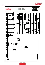
Страница 66: ...WIRING DIAGRAMS TBG 80 360LX ME TBG 80 360 ME 30 34 0006081328_202202 ENGLISH...

Страница 67: ...TBG 80 360LX ME TBG 80 360 ME 31 34 0006081328_202202 ENGLISH...

Страница 68: ...TBG 80 360LX ME TBG 80 360 ME I1 I2 BA I4 I3 32 34 0006081328_202202 ENGLISH...

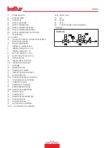
Страница 69: ...FAN MOTOR CONTACTOR MV FAN MOTOR N1 ELECTRONIC REGULATOR P M MAXIMUM PRESSURE SWITCH P1 HOUR METER PA AIR PRESSURE SWITCH Pm MINIMUM PRESSURE SWITCH S1 START STOP SWITCH S2 RELEASE BUTTON SG1 2 MAIN D...

Страница 70: ...34 34 0006081328_202202 ENGLISH...

Страница 71: ......

Страница 72: ...Il presente catalogo riveste carattere puramente indicativo La casa pertanto si riserva ogni possibilit di modifica dei dati tecnici e di quant altro in esso riportato Information contained in this c...

Отзывы: