background image

www.balluff.com

2

Installation (continued)

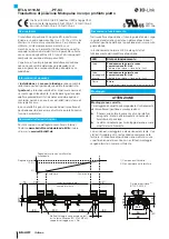
In order to avoid the development of resonant 

frequencies from vibration loads, we 

recommend arranging the mounting clamps at 

irregular intervals.

The transducer is electrically isolated from the machine 

with the supplied insulating bushes.

1. 

Guide the transducer into the mounting clamps.

2. 

Attach transducer to the base using mounting screws 

(tighten screws in the clamps with a max. 2 Nm).

3. 

Insert magnet (accessories).

The micropulse transducer in profile housing is 

suitable both for floating, i.e. non-contacting 

magnets, and for captive magnets.

Cable routing

Defined ground!

The transducer and the control cabinet must be 

at the same ground potential.

Magnetic fields

The position measuring system is a magnetostrictive 

system. It is important to maintain adequate distance 

between the transducer and strong, external magnetic 

fields.

Cable routing

Do not route the cable between the transducer, controller, 

and power supply near high voltage cables (inductive stray 

noise is possible).

Cable length

Cable length max. 20 m.

Startup

  DANGER

Uncontrolled system movement

When starting up, if the position measuring system is part 
of a closed loop system whose parameters have not yet 
been set, the system may perform uncontrolled 
movements. This could result in personal injury and 
equipment damage.


Persons must keep away from the system's 
hazardous zones.


Startup must be performed only by trained technical 
personnel.


Observe the safety instructions of the equipment or 
system manufacturer.

1. 

Check connections for tightness and correct polarity. 

Replace damaged connections.

2. 

Turn on the system.

3. 

Check measured values and adjustable parameters 

(especially after replacing the transducer or after repair 

by the manufacturer).

The calibration procedure is described in the 

comprehensive user's guide.

Operating notes


– Check the function of the transducer and all associated 

components on a regular basis.


– Take the position measuring system out of operation 

whenever there is a malfunction.


– Secure the system against unauthorized use.

english

No. 891254 E 

.

 Edition 1209; Subject to modification.

BTL6-U110-M _ _ _ _ -PF-S4

Micropulse Transducer in a Flat Profile Housing

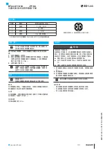
Electrical connection

Pin

Color

BTL6-U110-...S4

1

2

3

4

Pin assignment of S4 connector (view of connector pins of 

transducer)

1

Brown

L+ (18

30 V)

2

-

Not used 1)

3

Blue

L

-

 (GND)

4

Black

C/Q (Communication line)

1) Unassigned leads can be connected to GND on the controller side but not to the shield.

Содержание BTL6-U110-M****-PF-S4 series

Страница 1: ...BTL6 U110 M_ _ _ _ PF S4 deutsch Kurzanleitung english Condensed guide fran ais Notice r sum e italiano Istruzioni brevi espa ol Instrucciones breves...

Страница 2: ...Dieser Positionsgeber definiert die zu messende Position auf dem Wellenleiter Im Normalbetrieb zeigt die LED die Betriebszust nde des Wegaufnehmers an LED Betriebszustand Gr n Normalfunktion ohne IO...

Страница 3: ...e und wenn die Wegmess einrichtung Teil eines Regelsystems ist dessen Parame ter noch nicht eingestellt sind kann das System unkon trollierte Bewegungen ausf hren Dadurch k nnen Personen gef hrdet und...

Страница 4: ...ition to be measured on the waveguide In normal operation the LED indicates the operating states of the transducer LED Operating state Green Normal function without IO Link communication Magnet is wit...

Страница 5: ...suring system is part of a closed loop system whose parameters have not yet been set the system may perform uncontrolled movements This could result in personal injury and equipment damage Persons mus...

Страница 6: ...ce le long du guide d ondes Le capteur de position d termine la position mesurer sur le guide d ondes En fonctionnement normal la LED indique les tats de fonctionnement du capteur de d placement LED E...

Страница 7: ...sque le syst me de mesure de d placement fait partie int grante d un syst me de r gulation dont les param tres n ont pas encore t r gl s des mouvements incontr l s peuvent survenir De tels mouvements...

Страница 8: ...e da misurare sulla guida d onda In funzionamento normale il LED indica gli stati di funzionamento del trasduttore di posizione LED Stato di funzionamento Verde Funzionamento normale senza comunicazio...

Страница 9: ...parte di un sistema di regolazione i cui parametri non sono ancora stati impostati il sistema pu eseguire movimenti incontrollati Ci potrebbe causare pericolo per le persone e danni materiali Le perso...

Страница 10: ...posici n define la posici n que se ha de medir en el gu aondas En el servicio normal el LED indica los estados de servicio del transductor de desplazamiento LED Estado de servicio Verde Funcionamiento...

Страница 11: ...dos durante la puesta en servicio y si el dispositivo de medici n de desplazamiento forma parte de un sistema de regulaci n cuyos par metros todav a no se han configurado Con ello se puede poner en pe...

Страница 12: ...tl6 service balluff de LED IO Link IO Link 2004 108 EG EMC EMC EN 61000 6 1 EN 61000 6 2 EN 61000 6 3 EN 61000 6 4 E227256 13 73 73 80 80 250 250 15 50 34 8 68 24 8 20 8 M12 1 2 1 100 0 BTL5 P 3800 2...

Страница 13: ...www balluff com 2 1 2 2 Nm 3 20 m 1 2 3 891254 CH 1209 BTL6 U110 M_ _ _ _ PF S4 BTL6 U110 S4 1 2 3 4 S4 1 L 18 30 V 2 1 3 L GND 4 C Q 1 GND...

Страница 14: ......

Страница 15: ......

Страница 16: ...e 9 73765 Neuhausen a d F Phone 49 7158 173 370 Fax 49 7158 173 691 service balluff de US Service Center USA Balluff Inc 8125 Holton Drive Florence KY 41042 Phone 859 727 2200 Toll free 1 800 543 8390...

Отзывы: