background image

1

Intended use

The BTL6 Micropulse Transducer, together with a machine 

controller (e.g. PLC) and an IO-Link master, comprises a 

position measuring system. Flawless function in 

accordance with the specifications in the technical data is 

ensured only when using original BALLUFF accessories. 

Use of any other components will void the warranty.

Opening the transducer or non-approved use are not 

permitted and will result in the loss of warranty and liability 

claims against the manufacturer.

General safety notes

Installation

 and 

startup

 may only be performed by 

trained specialists.

The 

operator

 is responsible for ensuring that local safety 

regulations are observed. In particular, the operator must 

take steps to ensure that a defect in the position 

measuring system will not result in hazards to persons or 

equipment.

If defects and unresolvable faults occur in the transducer,  

it should be taken out of service and secured against 

unauthorized use.

Downloading further instructions

A complete user's guide can be downloaded from the 

Internet at 

www.balluff.com/downloads-btl6

 or 

requested via e-mail from 

[email protected]

.

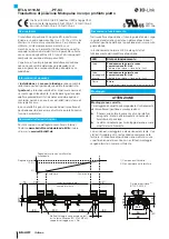
Dimensions and function

The transducer contains the waveguide. A magnet is 

moved along the waveguide. This magnet defines the 

position to be measured on the waveguide.

In normal operation the LED indicates the operating states 

of the transducer.

LED

Operating state

Green

Normal function without IO-Link 

communication

Magnet is within the limits.

Green
flashing
inversely

Normal function with IO-Link 

communication

Magnet is within the limits.

Red

Error

No magnet or magnet outside the limits.

Installation

NOTICE!

Improper installation

Improper installation can compromise the function of the 
transducer and result in damage.


For this reason, ensure that no strong electrical or 
magnetic fields are present in the immediate vicinity 
of the transducer.


The recommended spacing for the installation must 
be strictly observed.

Any orientation is permitted. Mount the transducer on a 

level surface of the machine using the provided mounting 

clamps and cylinder-head screws. A sufficient number of 

mounting clamps is supplied.

english

EU Directive 2004/108/EG (EMC Directive) and EMC law

Noise immunity: EN 61000-6-1 / EN 61000-6-2

Emission: EN 61000-6-3 / EN 61000-6-4

File no.

E227256

13

73

73

~80

~80

~250

~250

15

50

34.8

68

24.8

20.8

M12

1) Unusable area
2) Not included in scope of 

delivery

1)

Nominal length =
Measuring range

Null point

End point

Output signal rising:

Error signal

100 %

0 %

BTL5-P-3800-2 magnet

1)

Mounting clamps with insulating bushes

and ISO 4762 M5x25 cylinder-head screws,

max. tightening torque 2 Nm

LED

2)

BTL6-U110-M _ _ _ _ -PF-S4

Micropulse Transducer in a Flat Profile Housing

2)

Содержание BTL6-U110-M****-PF-S4 series

Страница 1: ...BTL6 U110 M_ _ _ _ PF S4 deutsch Kurzanleitung english Condensed guide fran ais Notice r sum e italiano Istruzioni brevi espa ol Instrucciones breves...

Страница 2: ...Dieser Positionsgeber definiert die zu messende Position auf dem Wellenleiter Im Normalbetrieb zeigt die LED die Betriebszust nde des Wegaufnehmers an LED Betriebszustand Gr n Normalfunktion ohne IO...

Страница 3: ...e und wenn die Wegmess einrichtung Teil eines Regelsystems ist dessen Parame ter noch nicht eingestellt sind kann das System unkon trollierte Bewegungen ausf hren Dadurch k nnen Personen gef hrdet und...

Страница 4: ...ition to be measured on the waveguide In normal operation the LED indicates the operating states of the transducer LED Operating state Green Normal function without IO Link communication Magnet is wit...

Страница 5: ...suring system is part of a closed loop system whose parameters have not yet been set the system may perform uncontrolled movements This could result in personal injury and equipment damage Persons mus...

Страница 6: ...ce le long du guide d ondes Le capteur de position d termine la position mesurer sur le guide d ondes En fonctionnement normal la LED indique les tats de fonctionnement du capteur de d placement LED E...

Страница 7: ...sque le syst me de mesure de d placement fait partie int grante d un syst me de r gulation dont les param tres n ont pas encore t r gl s des mouvements incontr l s peuvent survenir De tels mouvements...

Страница 8: ...e da misurare sulla guida d onda In funzionamento normale il LED indica gli stati di funzionamento del trasduttore di posizione LED Stato di funzionamento Verde Funzionamento normale senza comunicazio...

Страница 9: ...parte di un sistema di regolazione i cui parametri non sono ancora stati impostati il sistema pu eseguire movimenti incontrollati Ci potrebbe causare pericolo per le persone e danni materiali Le perso...

Страница 10: ...posici n define la posici n que se ha de medir en el gu aondas En el servicio normal el LED indica los estados de servicio del transductor de desplazamiento LED Estado de servicio Verde Funcionamiento...

Страница 11: ...dos durante la puesta en servicio y si el dispositivo de medici n de desplazamiento forma parte de un sistema de regulaci n cuyos par metros todav a no se han configurado Con ello se puede poner en pe...

Страница 12: ...tl6 service balluff de LED IO Link IO Link 2004 108 EG EMC EMC EN 61000 6 1 EN 61000 6 2 EN 61000 6 3 EN 61000 6 4 E227256 13 73 73 80 80 250 250 15 50 34 8 68 24 8 20 8 M12 1 2 1 100 0 BTL5 P 3800 2...

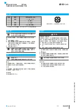
Страница 13: ...www balluff com 2 1 2 2 Nm 3 20 m 1 2 3 891254 CH 1209 BTL6 U110 M_ _ _ _ PF S4 BTL6 U110 S4 1 2 3 4 S4 1 L 18 30 V 2 1 3 L GND 4 C Q 1 GND...

Страница 14: ......

Страница 15: ......

Страница 16: ...e 9 73765 Neuhausen a d F Phone 49 7158 173 370 Fax 49 7158 173 691 service balluff de US Service Center USA Balluff Inc 8125 Holton Drive Florence KY 41042 Phone 859 727 2200 Toll free 1 800 543 8390...

Отзывы: