BTL5-S1_ _-M/U_ _ _ _-K-SR32/K_ _
Micropulse Linear Transducer - Rod Style
5
english
When routing the cable between the
transducer, controller and power
supply, avoid proximity to high volt-
age lines to prevent noise coupling.
Especially critical is inductive noise
caused by AC harmonics (e.g. from
phase-control devices), against
which the cable shield provides only
limited protection.
Position information is sent over the
RS 485/422 interface as synchro-
nous serial data (SSD) to the host
controller. High noise immunity is
assured by the differential drivers
used for sending and receiving sig-
nals.
Cable length max. 400 m ;
Ø 6 to 8 mm. The clock frequency is
a function of the cable length:
BKS Connector,
View of solder end
of connector body
BKS-S 32M-00
or BKS-S 33M-00
Fig. 4-1: Pin arrangement BKS on
BTL
Cable length
Clock frequency
< 50 m
< 500 kHz
< 100 m
< 400 kHz
< 200 m
< 200 kHz
< 400 m
< 100 kHz
Table 4-1: Clock frequency vs.
cable length
Pin
Cable
BTL5-S1_ _...
Interface signals
1
YE yellow
+Clk
2
GY gray
+Data
3
PK pink
–Clk
4
not used
➀
5
GN green
–Data
Supply voltage (external)
6
BU blue
GND
7
BN brown
+24 V
8
WH white
do not connect!
Caution!
False data will result from
reversing the +Clk and –Clk inputs.
Table 4-2: Wiring
➀
Unused leads can be tied to
GND on the control side, but they
must never be connected to the
shield.
3
Installation (cont.)
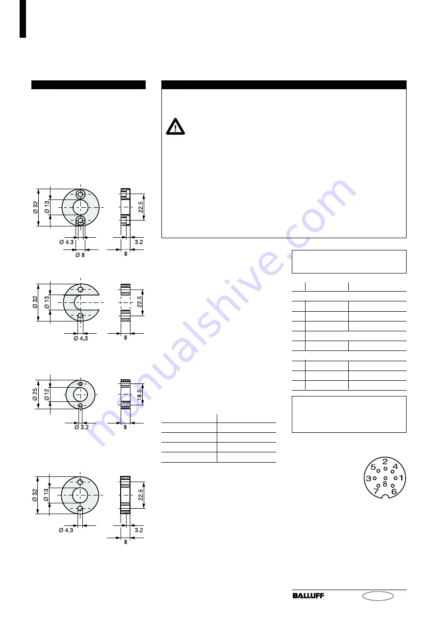
Fig. 3-4: Magnet (optional)
BTL-P-1013-4R
3.3
Magnets, Installation
A magnet is required for each trans-
ducer. This must be ordered sepa-
rately.
➥
➥
➥
➥
➥
Fig. 3-4.
For mounting the magnet we rec-
ommend to use non-magnetizable
material.
➥
➥
➥
➥
➥
Fig. 3-1.
BTL-P-1013-4S
BTL-P-1012-4R
Fig 3-5: Spacer
4
Wiring
Note the following when mak-
ing electrical connections:
System and control cabi-
net must be at the same
ground potential.
To ensure the electromagnetic
compatibility (EMC) which Balluff
warrants with the CE Mark, the
following instructions must be
strictly followed.
BTL transducer and the controller
must be connected using
shielded cable.
Shielding: Copper filament
braided, 80% coverage.
The shield must be tied to the
connector housing in the BKS
connector (
➥
➥
➥
➥
➥
Fig. 6-1); see in-
structions accompanying the con-
nector.
In the cable version the cable shield
is connected to the housing in the
PG fitting.
The cable shield must be grounded
on the control side, i.e., connected
to the protection ground.
Pin assignments can be found in
➥
➥
➥
➥
➥
Table 4-2. Connections on the
controller side may vary according
to the controller and configuration
used.


