background image

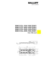
Balluff Network Interface / CC-Link BNI-CCL-104/202/302/305-100-Z001 


www.balluff.com


2


Nodes for the user 

1.1 About this guide 

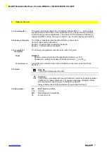
  This guide describes the Balluff CC-Link Field bus Module BNI CCL-… which enables 

expanded communication down to the lowest level so as to provide improved process 
optimizing and preventive maintenance. This module is IP67 protected and features a 
rugged metal IP67 housing. The device is ideal for use in harsh industrial environments.  
 

1.2 Structure of the guide 

  The Guide is organized so that the sections build on one another. 

Section 2. Basic safety informations. 
Section 3: The main steps for installing the device. 
Section 4: T echnical data for the device. 
… 

1.3 Typographical 

Conventions 
 

  The following typographical conventions are used in this guide.  

Syntax 


Numbers: 

  Decimal numbers are shown without additional indicators (e.g. 123), 

  Hexadecimal numbers are shown with additional indicator 

hex

 (e.g. 00

hex


Cross-references 

  Cross-references indicate where further information on the topic can be found ("see 

Section 4 “). 


1.4 Symbols 


Note, tip 

This symbol indicates general notes. 


Attention! 

This symbol in connection with the word "Attention" warns of a possible hazardous 
situation for the health of persons or for equipment damage. Disregard of these 
warning notes may result in injury or damage to equipment. 

Always observe the described measures for preventing this danger. 


1.5 Abbreviations 

  BNI        Balluff Network Interface 

CCL       CC-Link 
EMC      Electromagnetic Compatibility 
FE 

Function Ground 


Содержание BNI CCL-104-100-Z001

Страница 1: ...BNI CCL 104 100 Z001 BNI CCL 202 100 Z001 BNI CCL 302 100 Z001 BNI CCL 305 100 Z001 User Manual...

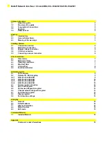
Страница 2: ...4 3 Operating conditions 7 4 4 Electrical Data 7 4 5 CC Link Port 8 4 6 Function Indicators 8 5 Remote signals 5 1 Port overview 9 5 2 Remote I O Data mapping 9 5 2 1 BNI CCL 104 100 Z001 9 5 2 2 BNI...

Страница 3: ...4 Technical data for the device 1 3 Typographical Conventions The following typographical conventions are used in this guide Syntax Numbers Decimal numbers are shown without additional indicators e g...

Страница 4: ...g the appropriate measures before using The device may be operated only using an approved power supply see 0 Technical Data Only approved cables may be used Operations and testing The operator is resp...

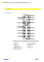
Страница 5: ...interfaces are shown in the following chapters 1 Mounting hole 2 CC Link Bus Input 3 Display 4 Power supply IN 5 Standard input Port X4 X5 6 Standard Input Port X6 X7 7 Standard Output Port Y4 Y5 8 S...

Страница 6: ...ommunication supply 5 24V Actuator supply Power Out 7 8 Mini Change 5 pin female PIN Signal Description 1 0 V Actuator supply 2 0 V Sensor and bus communication supply 3 FE Function Ground 4 24V Senso...

Страница 7: ...A Line blue 3 5 Connecting sensors actuators 8 I O ports are provided for connecting actuators and sensors Standard I O port M12 A coded female Input Output Combined Inputs Outputs PIN Function Functi...

Страница 8: ...nput ports Output ports M12 A coded 8 x female Dimensions W x H x D in mm 68 x 224 x 30 9 Mounting type 2 hole screw mount Ground strap attachment M4 Weight Approx 580gr 4 3 Operating conditions Opera...

Страница 9: ...s Status LED LED Indicator Function LED 1 Green Red Module Status LED 2 Green Red UA Power supply under voltage LED 6 Green Communication status LED 7 Red Communication error LED indicators input port...

Страница 10: ...Port 3 Pin 4 RXn7 Port 3 Pin 2 RXn8 Port 4 Pin 4 RXn9 Port 4 Pin 2 RXnA Port 5 Pin 4 RXnB Port 5 Pin 2 RXnC Port 6 Pin 4 RXnD Port 6 Pin 2 RXnE Port 7 Pin 4 RXnF Port 7 Pin 2 RX n 1 0 to RX n 1 7 Unus...

Страница 11: ...4 RYn2 Port 2 Pin 4 RXn3 Port 3 Pin 4 RYn3 Port 3 Pin 4 RXn4 Port 4 Pin 4 RYn4 Port 4 Pin 4 RXn5 Port 5 Pin 4 RYn5 Port 5 Pin 4 RXn6 Port 6 Pin 4 RYn6 Port 6 Pin 4 RXn7 Port 7 Pin 4 RYn7 Port 7 Pin 4...

Страница 12: ...in 4 RXn7 Port 3 Pin 2 RYn7 Port 3 Pin 2 RXn8 Port 4 Pin 4 RYn8 Port 4 Pin 4 RXn9 Port 4 Pin 2 RYn9 Port 4 Pin 2 RXnA Port 5 Pin 4 RYnA Port 5 Pin 4 RXnB Port 5 Pin 2 RYnB Port 5 Pin 2 RXnC Port 6 Pin...

Страница 13: ...d RX n 1 8 Initial data processing request flag RY n 1 8 Initial data processing request flag RX n 1 9 Initial data setting completion flag RY n 1 9 Initial data setting completion flag RX n 1 A Error...

Страница 14: ...10 9 8 7 6 5 4 3 2 1 0 P7 P2 P7 P4 P6 P2 P6 P4 P5 P2 P5 P4 P4 P2 P4 P4 P3 P2 P3 P4 P2 P2 P2 P4 P1 P2 P1 P4 P0 P2 P0 P4 Pn 0 Input Pm 1 Output 5 8 Display register 15 14 13 12 11 10 9 8 7 6 5 4 3 2 1 0...

Страница 15: ...the communication speed is set directly on the BNI CCL devices 6 2 Default settings Address 3 Communication speed 625kbps 6 3 Display informations 6 4 Menu structure Start up screen 2 sec address win...

Страница 16: ...peed is set directly on the BNI CCL devices push scroll to the next screen long push fast scroll is activated long push S for 3 seconds edit mode is activated display informations flashing leave the e...

Страница 17: ...CC Link BNI CCL 104 202 302 305 100 Z001 www balluff com 16 7 Included Material 7 1 Included Material The BNI CCL consists of the following components IO block 4 blind plugs M12 Ground strap Screw M4...

Страница 18: ...odule max 16 Inputs Outputs 305 IP 67 Input module 8 Inputs 8 Outputs Variant 100 Display version Mechanical version Z001 Die cast zinc housing Material 1 Balluff housing version Bus In 1 x M12x1 inte...

Страница 19: ...Balluff Network Interface CC Link BNI CCL 104 202 302 305 100 Z001 www balluff com 18...

Страница 20: ...104 202 302 305 100 Z001 www balluff com 19 www balluff com Balluff GmbH Schurwaldstrasse 9 73765 Neuhausen a d F Germany Tel 49 7158 173 0 Fax 49 7158 5010 balluff balluff de n www balluff com Nr 870...

Отзывы: