background image

Balluff Network Interface / CC-Link BNI-CCL-104/202/302/305-100-Z001 


www.balluff.com


10


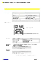
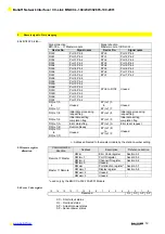
Remote signals / Data mapping 

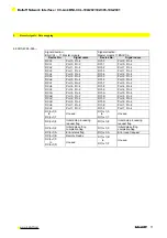
5.2.2 BNI CCL-202-… 


BNI CCL-202-100-Z001 


  Signal direction: 

BNI-CCL-… 

 Master module 

Signal direction: 
Master module 

 BNI-CCL-… 


Device No.


Signal name


Device No.


Signal name


  RXn0


Port 0, Pin 4 

RYn0 

Port 0, Pin 4


  RXn1


Port 1, Pin 4 

RYn1


Port 1, Pin 4


  RXn2


Port 2, Pin 4


RYn2


Port 2, Pin 4


  RXn3


Port 3, Pin 4


RYn3


Port 3, Pin 4


  RXn4


Port 4, Pin 4


RYn4


Port 4, Pin 4


  RXn5


Port 5, Pin 4


RYn5


Port 5, Pin 4


  RXn6


Port 6, Pin 4


RYn6


Port 6, Pin 4


  RXn7


Port 7, Pin 4


RYn7


Port 7, Pin 4


  RXn8 

   to  
RX(n+1)7 

Unused 

RYn8 
   to  
RY(n+1)7


Unused 


RX(n+1)8 

Initial data processing 
request flag 

RY(n+1)8 

Initial data processing 
request flag 


RX(n+1)9 

Initial data setting 
completion flag 

RY(n+1)9 

Initial data setting 
completion flag 


  RX(n+1)A 

Error status flag 

RY(n+1)A 

Error reset request 


  RX(n+1)B 

Remote Ready 


  RX(n+1)C 

      to 
RX(n+1)F) 

Unused 

RY(n+1)B 
      to 
RY(n+1)F 

Unused 


Содержание BNI CCL-104-100-Z001

Страница 1: ...BNI CCL 104 100 Z001 BNI CCL 202 100 Z001 BNI CCL 302 100 Z001 BNI CCL 305 100 Z001 User Manual...

Страница 2: ...4 3 Operating conditions 7 4 4 Electrical Data 7 4 5 CC Link Port 8 4 6 Function Indicators 8 5 Remote signals 5 1 Port overview 9 5 2 Remote I O Data mapping 9 5 2 1 BNI CCL 104 100 Z001 9 5 2 2 BNI...

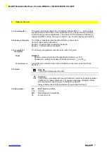
Страница 3: ...4 Technical data for the device 1 3 Typographical Conventions The following typographical conventions are used in this guide Syntax Numbers Decimal numbers are shown without additional indicators e g...

Страница 4: ...g the appropriate measures before using The device may be operated only using an approved power supply see 0 Technical Data Only approved cables may be used Operations and testing The operator is resp...

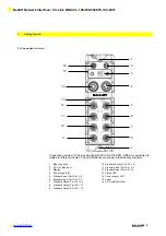
Страница 5: ...interfaces are shown in the following chapters 1 Mounting hole 2 CC Link Bus Input 3 Display 4 Power supply IN 5 Standard input Port X4 X5 6 Standard Input Port X6 X7 7 Standard Output Port Y4 Y5 8 S...

Страница 6: ...ommunication supply 5 24V Actuator supply Power Out 7 8 Mini Change 5 pin female PIN Signal Description 1 0 V Actuator supply 2 0 V Sensor and bus communication supply 3 FE Function Ground 4 24V Senso...

Страница 7: ...A Line blue 3 5 Connecting sensors actuators 8 I O ports are provided for connecting actuators and sensors Standard I O port M12 A coded female Input Output Combined Inputs Outputs PIN Function Functi...

Страница 8: ...nput ports Output ports M12 A coded 8 x female Dimensions W x H x D in mm 68 x 224 x 30 9 Mounting type 2 hole screw mount Ground strap attachment M4 Weight Approx 580gr 4 3 Operating conditions Opera...

Страница 9: ...s Status LED LED Indicator Function LED 1 Green Red Module Status LED 2 Green Red UA Power supply under voltage LED 6 Green Communication status LED 7 Red Communication error LED indicators input port...

Страница 10: ...Port 3 Pin 4 RXn7 Port 3 Pin 2 RXn8 Port 4 Pin 4 RXn9 Port 4 Pin 2 RXnA Port 5 Pin 4 RXnB Port 5 Pin 2 RXnC Port 6 Pin 4 RXnD Port 6 Pin 2 RXnE Port 7 Pin 4 RXnF Port 7 Pin 2 RX n 1 0 to RX n 1 7 Unus...

Страница 11: ...4 RYn2 Port 2 Pin 4 RXn3 Port 3 Pin 4 RYn3 Port 3 Pin 4 RXn4 Port 4 Pin 4 RYn4 Port 4 Pin 4 RXn5 Port 5 Pin 4 RYn5 Port 5 Pin 4 RXn6 Port 6 Pin 4 RYn6 Port 6 Pin 4 RXn7 Port 7 Pin 4 RYn7 Port 7 Pin 4...

Страница 12: ...in 4 RXn7 Port 3 Pin 2 RYn7 Port 3 Pin 2 RXn8 Port 4 Pin 4 RYn8 Port 4 Pin 4 RXn9 Port 4 Pin 2 RYn9 Port 4 Pin 2 RXnA Port 5 Pin 4 RYnA Port 5 Pin 4 RXnB Port 5 Pin 2 RYnB Port 5 Pin 2 RXnC Port 6 Pin...

Страница 13: ...d RX n 1 8 Initial data processing request flag RY n 1 8 Initial data processing request flag RX n 1 9 Initial data setting completion flag RY n 1 9 Initial data setting completion flag RX n 1 A Error...

Страница 14: ...10 9 8 7 6 5 4 3 2 1 0 P7 P2 P7 P4 P6 P2 P6 P4 P5 P2 P5 P4 P4 P2 P4 P4 P3 P2 P3 P4 P2 P2 P2 P4 P1 P2 P1 P4 P0 P2 P0 P4 Pn 0 Input Pm 1 Output 5 8 Display register 15 14 13 12 11 10 9 8 7 6 5 4 3 2 1 0...

Страница 15: ...the communication speed is set directly on the BNI CCL devices 6 2 Default settings Address 3 Communication speed 625kbps 6 3 Display informations 6 4 Menu structure Start up screen 2 sec address win...

Страница 16: ...peed is set directly on the BNI CCL devices push scroll to the next screen long push fast scroll is activated long push S for 3 seconds edit mode is activated display informations flashing leave the e...

Страница 17: ...CC Link BNI CCL 104 202 302 305 100 Z001 www balluff com 16 7 Included Material 7 1 Included Material The BNI CCL consists of the following components IO block 4 blind plugs M12 Ground strap Screw M4...

Страница 18: ...odule max 16 Inputs Outputs 305 IP 67 Input module 8 Inputs 8 Outputs Variant 100 Display version Mechanical version Z001 Die cast zinc housing Material 1 Balluff housing version Bus In 1 x M12x1 inte...

Страница 19: ...Balluff Network Interface CC Link BNI CCL 104 202 302 305 100 Z001 www balluff com 18...

Страница 20: ...104 202 302 305 100 Z001 www balluff com 19 www balluff com Balluff GmbH Schurwaldstrasse 9 73765 Neuhausen a d F Germany Tel 49 7158 173 0 Fax 49 7158 5010 balluff balluff de n www balluff com Nr 870...

Отзывы: