Balluff Network Interface / CC-Link BNI-CCL-104/202/302/305-100-Z001
6
3
Getting Started
3.4 CC-Link Connection
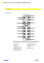
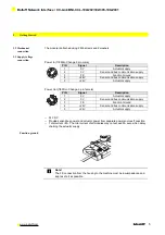
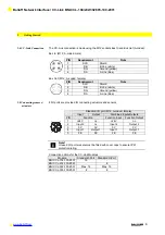
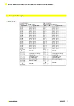
The CC-Link connection is made using the M12 sockets Bus In and Bus Out (A-coded).
Bus In: (M12, A-coded, male)
PIN
Requirement
Note
1
SLD
Shield
2
DB
B Line (white)
3
DG
Ground (yellow)
4
DA
A Line (blue)
Bus Out: (M12, A-coded, female)
PIN
Requirement
Note
1
SLD
Shield
2
DB
B Line (white)
3
DG
Ground (yellow)
4
DA
A Line (blue)
3.5 Connecting sensors /
actuators
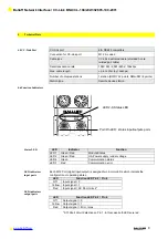
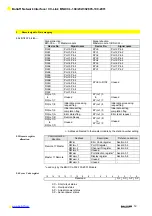
8 I/O ports are provided for connecting actuators and sensors
Standard I/O port (M12, A-coded, female)
Input
Output
Combined Inputs/Outputs
PIN
Function
Function Input
Function Output
1
+24 V
n.c.
+24V
n.c.
2
Input 2
n.c.
Input 2
Output 2
3
0V
0V
0V
0V
4
Input 1
Output 1
Input 1
Output 1
5
FE
FE
FE
FE
Note!
Unused I/O port sockets must be fitted with cover caps to ensure IP67
protection rating.
Connection options for the CC-Link Modules
Module
Standard I-Port
Standard O-Port
BNI CCL-104-100-Z001
16
-
BNI CCL-202-100-Z001
-
8
BNI CCL-302-100-Z001
Max. 16
Max. 16
BNI CCL-305-100-Z001
8
8

