Input / Output 4-25
MN1903
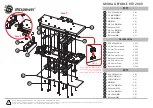
The pin connections in the example are described below:
Breakout
module
connector
Pin
Name of
signal
Function
Connection on drive
(Note: drive may be
labelled differently)
X7
1
Demand0
Command signal for axis 0
input
2
AGND
Command signal for axis 0
Demand- input
X12
-
Encoder
Position feedback
Encoder out
(or direct from motor)
X1
2
DIN12
Error input
Error output
12
Common2
Error input
Error output
X8
7
Relay COM
Common connection of relay
Enable input
6
Relay NO
Normally open connection
of relay
Amplifier/Digital
Ground
Table 4 - Connector details for minimum system wiring shown in Figure 9
This completes the input/output wiring.
You should read the following sections in
sequence before using the NextMove PCI.
Содержание NextMove PCI
Страница 1: ...NextMove PCI Motion Controller MOTION CONTROL Installation Manual 3 02 MN1903...
Страница 2: ......
Страница 6: ...iv Contents MN1903...
Страница 16: ...3 4 Basic Installation MN1903...
Страница 42: ...4 26 Input Output MN1903...
Страница 57: ...Operation 5 15 MN1903 Figure 11 The NextMove PCI servo loop...
Страница 74: ...5 32 Operation MN1903...
Страница 90: ...A 8 Accessories MN1903...
Страница 91: ......