background image

4-24 Input / Output

MN1903

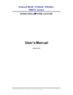
4.9 Connection summary - minimum system wiring

As a guide, Figure 9 shows an example of the typical minimum wiring required to allow the
NextMove PCI and a single axis servo amplifier (motor drive) to work together. Details of the
connector pins are shown in Table 4.

NextMove PCI

100-pin
connecting
cable

Host PC

Breakout module

Servo amplifier (axis 0)

Encoder output
from drive or
motor

Error out

Gnd*

Enable*

Demand -

X7

X8

X1
2

X1

* Note:

This diagram shows the relay contacts

being used as a switch across the servo
amplifier’s enable input.

If the servo amplifier requires a 24V

enable signal then:

- Connect

Gnd

to CGND (X8 pin 9).

- Connect

Enable

to one side of the relay

(X8 pin 5 for normally closed operation).

- Connect the other side of the relay (X8

pin 7) to USR V+ (X8 pin 8 ).

Figure 9 - Example minimum system wiring

Содержание NextMove PCI

Страница 1: ...NextMove PCI Motion Controller MOTION CONTROL Installation Manual 3 02 MN1903...

Страница 2: ......

Страница 3: ...NextMove PCI card 3 3 3 3 2 NextMove PCI Expansion card and CAN Bracket board 3 3 4 Input Output 4 1 4 1 Outline 4 1 4 2 100 pin edge connector 4 1 4 2 1 100 pin connector pin assignment 4 2 4 3 Anal...

Страница 4: ...s card 5 8 5 3 3 Selecting a scale 5 9 5 3 4 Setting the drive enable output 5 10 5 3 5 Testing the drive enable output 5 11 5 4 Servo axis testing and tuning 5 12 5 4 1 Testing the drive command outp...

Страница 5: ...tal inputs X3 7 2 7 1 6 Digital outputs X4 7 3 7 1 7 Relay output X8 7 3 7 1 8 Encoder interfaces X12 X16 7 3 7 1 9 Stepper outputs X10 X11 7 4 7 1 10 CANopen interface X17 7 4 7 1 11 Baldor CAN inter...

Страница 6: ...iv Contents MN1903...

Страница 7: ...be held responsible for any expense including installation and removal inconvenience or consequential damage including injury to any person or property caused by items of our manufacture or sale Some...

Страница 8: ...nly qualified personnel should attempt to program start up or troubleshoot this equipment WARNING The stop input to this equipment should not be used as the single means of achieving a safety critical...

Страница 9: ...addition MintMT includes a wide range of powerful commands for complex applications Standard features include H Control of up to eight axes H Point to point moves software cams and gearing H 20 digita...

Страница 10: ...ons to be written that communicate with the NextMove PCI H Embedded Developer Libraries Allows embedded C31 applications to be developed using the Texas Instruments TMS320C3x compiler This manual is i...

Страница 11: ...ms to the storage humidity and temperature specifications shown in section 3 2 2 2 1 Identifying the catalog number NextMove PCI cards are available with different specifications As a reminder of whic...

Страница 12: ...ase ms millisecond s microsecond ns nanosecond Kbaud kilobaud the same as Kbit s in most applications MB megabytes CDROM Compact Disc Read Only Memory CTRL E on the PC keyboard press Ctrl then E at th...

Страница 13: ...32MB 64MB Hard disk space 40MB 60MB CD ROM A CD ROM drive Screen 800 x 600 256 colors 1024 x 768 256 colors Mouse A mouse or similar pointing device Operating system Windows 95 Windows 98 Windows ME W...

Страница 14: ...of this equipment depends upon its use in the appropriate environment The following points must be considered H The NextMove PCI must be installed in an enclosed cabinet located so that it can only b...

Страница 15: ...rd 8 Align the bottom of the card gold contacts with the slot and press the card firmly into the socket When correctly installed the card locks into place 9 Make sure that the top of the card is level...

Страница 16: ...3 4 Basic Installation MN1903...

Страница 17: ...l Input DOUT Digital Output AIN Analog Input AOUT Analog Output Connections to the NextMove PCI card are made using the 100 pin cable assembly and DIN rail mounted NextMove PCI Breakout module supplie...

Страница 18: ...2 CHB 63 Encoder 0 CHB 14 Encoder 2 CHB 64 Encoder 0 CHB 15 Encoder 2 CHZ 65 Encoder 0 CHZ 16 Encoder 2 CHZ 66 Encoder 0 CHZ 17 Encoder 3 CHA 67 Encoder 1 CHA 18 Encoder 3 CHA 68 Encoder 1 CHA 19 Enc...

Страница 19: ...7 83 USR V 34 DOUT6 84 DOUT5 35 DOUT4 85 CGND 36 DOUT3 86 DOUT2 37 DOUT1 87 CGND 38 DOUT0 88 Common2 39 DIN19 89 DIN17 40 DIN18 90 DIN16 41 DIN15 91 DIN13 42 DIN14 92 DIN12 43 DIN11 93 DIN9 44 DIN10 9...

Страница 20: ...esolution analog inputs The inputs are available on connector X6 on the NextMove PCI Breakout module H Four 14 bit resolution analog outputs The outputs are available on connector X7 on the NextMove P...

Страница 21: ...range software selectable 0 5V 5V 0 10V 10V Resolution 12 bit with sign accuracy 4 9mV 10V input Input impedance 5k Sampling frequency 2 5kHz Shielded twisted pairs should be used and connected as sho...

Страница 22: ...tMT ADC 0 Breakout module 3 1 2 X6 100 pin cable Figure 1 Analog input wiring AIN0 shown For differential inputs connect input lines to AIN and AIN Leave AGND unconnected For single ended inputs conne...

Страница 23: ...Shield Shield connection Description Four independent command outputs Output range 10VDC 0 1 Resolution 14 bit accuracy 1 22mV Output current 1mA maximum Update frequency Immediate MintMT and the Min...

Страница 24: ...om others which are active high If all inputs are similar then the commons can be connected together to form one common connection The arrangement of the inputs their common power connection and the c...

Страница 25: ...uts can be shared between axes and are programmable using the MintMT keyword OUTPUTACTIVELEVEL to determine their active level The outputs are driven by a module fitted to the NextMove PCI card Two mo...

Страница 26: ...INX 16 Common2 7 DIN17 INX 17 8 DIN18 INX 18 9 DIN19 INX 19 10 Shield Shield connection 11 NC 12 Common2 Common connection Description Eight general purpose optically isolated AC digital inputs Sampli...

Страница 27: ...ve low The digital inputs will be active when grounded 2V and will source a maximum of 8mA each Note Sustained input voltages above 28V will damage the inputs 4 4 2 Digital inputs X2 Location Breakout...

Страница 28: ...ctor X3 Pin Name MintMT keyword description 1 DIN0 INX 0 2 Common1 Common connection 3 Shield Shield connection 4 DIN1 INX 1 5 Common1 Common connection 6 Shield Shield connection 7 DIN2 INX 2 8 Commo...

Страница 29: ...e optically isolated digital outputs Output current 50mA maximum each output Update frequency Immediate Each optically isolated output is designed to source current from the customer supplied 12 24V s...

Страница 30: ...eakout module connector X5 Pin Name MintMT keyword description 1 Shield Shield connection 2 DOUT0 OUTX 0 3 DOUT1 OUTX 1 4 DOUT2 OUTX 2 5 DOUT3 OUTX 3 6 DOUT4 OUTX 4 7 DOUT5 OUTX 5 8 NC 9 NC 10 Shield...

Страница 31: ...o five incremental encoders may be connected to NextMove PCI Each input channel uses a MAX3095 differential line receiver with pull up resistors and terminators Encoders must provide either 5V differe...

Страница 32: ...s is equivalent to a maximum frequency for the A and B signals of 1 87MHz However the effect of cable length is shown in Table 3 Frequency Maximum cable length Frequency meters feet 1 3MHz 2 6 56 500k...

Страница 33: ...5V supply can be use to power the encoders by connecting pin 1 or 2 to pin 3 or 4 A link is provided for this purpose The total current requirement of the encoders must not exceed 500mA Check that th...

Страница 34: ...ormally non isolated and therefore does not need a power supply However it may be necessary for some Baldor CAN nodes to derive a 12 24V supply from the CAN cable For this reason X8 provides a conveni...

Страница 35: ...pin female D type connectors The stepper drive outputs can operate at up to 3MHz The signals from the NextMove PCI are at TTL levels but are converted to 5V differential drive signals by a circuit bo...

Страница 36: ...bility of an undetected error is 4 7x10 11 The default transmission rate is 125Kbit s although higher rates up to 1000Kbit s can be selected CAN is optimized for the transmission of small data packets...

Страница 37: ...CAN1 CANopen X17 CANopen connections are made using the breakout module connector X17 Location Breakout module connector X17 Pin Name Description 1 Shield Cable shield 2 CAN1 CAN channel 1 negative 3...

Страница 38: ...4 CAN2 0V Ground earth reference for CAN signal 5 CAN2 V CAN remote node power V 12 24V 6 NC 7 CAN2 CAN channel 2 positive 8 CAN2 CAN channel 2 negative Description Baldor proprietary CAN interface us...

Страница 39: ...ardware and software reset states should not be confused with the Mint keyword RESET which is used to clear axis errors Communications At power up the CAN controllers will be held in reset and will ha...

Страница 40: ...ing cable Host PC Breakout module Servo amplifier axis 0 Encoder output from drive or motor Error out Gnd Enable Demand Demand X7 X8 X12 X1 Note This diagram shows the relay contacts being used as a s...

Страница 41: ...axis 0 Demand input X12 Encoder Position feedback Encoder out or direct from motor X1 2 DIN12 Error input Error output 12 Common2 Error input Error output X8 7 Relay COM Common connection of relay En...

Страница 42: ...4 26 Input Output MN1903...

Страница 43: ...or separately within the packaging 5 1 1 Installing the driver software Windows 95 98 and ME 1 Turn on the PC During the start process Windows will detect the newly installed NextMove PCI card 2 When...

Страница 44: ...software Windows 2000 The Windows NT device driver is used with Windows 2000 but is installed differently 1 After installing the NextMove PCI card turn on the PC 2 Enter the BIOS and disable the Plug...

Страница 45: ...d should start automatically If the setup wizard does not appear select Run from the Windows Start menu and type d start where d represents the drive letter of the CDROM device Follow theon screeninst...

Страница 46: ...rkBench v5 WorkBench v5 WorkBench v5 will start and the Tip of the Day dialog will be displayed You can prevent the Tip of the Day dialog appearing next time by removing the check mark next to Show ti...

Страница 47: ...the top and select Do not scan serial ports Click Scan to search for the NextMove PCI When the search is complete click NextMove PCI card 0 and then click Select 4 A dialog box will appear to tell yo...

Страница 48: ...download the firmware The firmware will be downloaded to the NextMove PCI A dialog box may be displayed to tell you that WorkBench v5 has detected the new firmware Click OK to continue WorkBench v5 r...

Страница 49: ...The help file can be displayed at any time by pressing F1 On the left of the help window the Contents tab shows the tree structure of the help file each book contains a number of topics The Index tab...

Страница 50: ...ck the Edit Debug icon 2 Click in the Command window 3 Type the command CONFIG 0 _cfSTEPPER where 0 is the axis to be configured Press Enter to enter the value This immediately sets axis 0 to be a ste...

Страница 51: ...example MOVER 16000 Move Relative would rotate the motor by 16000 quadrature counts only four revolutions By setting a SCALE factor of 4000 the user unit becomes revolutions The more understandable c...

Страница 52: ...n either be a digital output or the relay 1 In the Toolbox click the Digital I O icon 2 At the bottom of the Digital I O screen click the Digital Outputs tab The left of the screen shows a column of y...

Страница 53: ...5 Testing the drive enable output 1 On the main WorkBench v5 toolbar click the Drive enable button Click the button again Each time you click the button the drive enable output is toggled When the bu...

Страница 54: ...Command window 4 Type TORQUE 0 5 where 0 is the axis demand output to be tested In this example this should cause a demand of 5 of maximum output 0 5V to be produced at the Demand 0 output breakout m...

Страница 55: ...proportional controller would simply multiply the amount of error by the Proportional gain and apply the result to the motor the further Demand gets ahead or behind you the more you press or release t...

Страница 56: ...d to reduce any overshoot If KVEL becomes too large it will amplify any noise on the velocity measurement and introduce oscillations H KINT This gain has a de stabilizing effect but a small amount can...

Страница 57: ...Operation 5 15 MN1903 Figure 11 The NextMove PCI servo loop...

Страница 58: ...hod explained in this section should allow you to gain good control of the motor but will not necessarily provide the optimum response without further fine tuning Unavoidably this requires a good unde...

Страница 59: ...s could be expressed in revolutions or other unit of your choice then those are the units that will be used here If you did not set a scale the amount you enter will be in encoder counts 6 Click in th...

Страница 60: ...value for KDERIV should be increased to add extra damping to the move If the overshoot is excessive or oscillation has occurred it may be necessary to reduce the value of KPROP Measured position Deman...

Страница 61: ...e 13 then the value for KDERIV should be decreased to reduce the damping of the move If the overdamping is excessive it may be necessary to increase the value of KPROP Measured position Demand positio...

Страница 62: ...the graph shows that the response reaches the demand quickly and only overshoots the demand by a small amount this can be considered an ideal response for most systems See Figure 14 Measured position...

Страница 63: ...With current controlled drives a non zero demand output is required to hold the load in the correct position to achieve zero following error Care is required when setting KINT since a high value will...

Страница 64: ...correct value for KVELFF you will need to know H The speed in revolutions per minute produced by the motor when a maximum demand 10V is applied to the drive H The setting for LOOPTIME The factory pre...

Страница 65: ...6 In the Move Type drop down box check that the move type is set to Trapezoid 7 Click intheDistancebox andenter adistance for the step move It is recommended to set a value that will cause the motor...

Страница 66: ...anges to the calculated value of KVELFF If the trace for Measured velocity appears above the trace for Demand velocity reduce the value of KVELFF If the trace for Measured velocity appears below the t...

Страница 67: ...er a starting value of 0 1 2 Click Go The NextMove PCI will perform the move and the motor will turn As the soon as the move is completed WorkBench v5 will download captured data from the NextMove PCI...

Страница 68: ...n Demand position Figure 16 Correct value of KPROP The two traces will probably appear with a small offset from each other Adjust KPROP by small amounts until the two traces appear on top of each othe...

Страница 69: ...connected from other machinery 1 Check that the Drive enable button is pressed 2 In the Toolbox click the Edit Debug icon 3 Click in the Command window 4 Type JOG 0 2 where 0 is the axis stepper outpu...

Страница 70: ...ction for example the Forward Limit In the following example digital input 1 will be set to trigger on a falling edge and allocated to the forward limit input of axis 0 1 In the Toolbox click the Digi...

Страница 71: ...changes to the NextMove PCI Note If required multiple inputs can be configured before clicking Apply 5 9 2 Digital output configuration The Digital Outputs tab allows you to define how each digital ou...

Страница 72: ...used Alternatively the information can be included in program files as part of the Startup block 1 In the Toolbox click the Edit Debug icon 2 On the main menu choose File New File A new program editin...

Страница 73: ...in menu choose File Open File Locate the file and click Open A Startup block should be included in every Mint program so that whenever a program is loaded and run the NextMove PCI will be correctly co...

Страница 74: ...5 32 Operation MN1903...

Страница 75: ...essage with comprehensive system information and selected attachments already in place You can add any additional message of your own and then send the e mail The PC must have email facilities to use...

Страница 76: ...cycling In software reset with no errors see section 4 8 All red cycling In software reset Power On Self Test POST error has occurred S1 green flashing Program is running OK S1 red flashing Program i...

Страница 77: ...that the connections between motor and drive are correct Use WorkBench v5 to perform the basic system tests see section 5 4 or 5 8 Ensure that while the controller is not in error the drive is enabled...

Страница 78: ...For setting up purposes following error detection may be disabled by setting FOLERRORMODE 0 Motor is under control but vibrates or overshoots during a move Servo loop gains may be set incorrectly See...

Страница 79: ...ard 175mm 6 875in long x 106 7mm 4 2in high Operating temperature 0 40 C 32 104 F ambient The host PC must have a spare 7 inch PCI card slot Additional slots will be required to accommodate expansion...

Страница 80: ...inputs X1 X2 Description Unit Value Type VDC Opto isolated AC inputs Input voltage Active high Nominal Minimum VDC 24 12 Input voltage Active low Nominal Maximum VDC 0 2 Input current approximate per...

Страница 81: ...urrent A 2 Maximum switching power 62 5VA 30W Maximum switching voltage 125VAC 60VDC Maximum switching current A 1 Contact resistance maximum m 100 Update interval Immediate 7 1 8 Encoder interfaces X...

Страница 82: ...z 3 Output voltage 5V Output current mA 20 max 7 1 10CANopen interface X17 Description Unit Value Signal 2 wire isolated Channels 1 Bit rate Kbit s 10 20 50 100 125 250 500 800 1000 Protocol CANopen 7...

Страница 83: ...uts drive command outputs and a relay However there are no CAN functions The electrical specification of the I O is the same as the main NextMove PCI card The card requires its own additional breakout...

Страница 84: ...ions to the expansion card s relay are present only on the breakout module attached to the expansion card A 1 2 Axis numbering when using expansion card s The main NextMove PCI card is available in 1...

Страница 85: ...powered Both red In hardware reset see section 4 8 Both green flashing alternately In software reset with no errors see section 4 8 Both red flashing alternately In software reset Power On Self Test...

Страница 86: ...PCI003 501 Breakout module Single part screw down terminals and signal conditioning PCI002 502 Breakout module Two part screw down terminals and signal conditioning CBL021 501 1 0m 100 pin cable to at...

Страница 87: ...ption OPT026 506 Allows NextMove PCI to connect to a NextMove PC system Note If the NextMove PC Breakout module is also being used the digital input banks use one common connection The USR V supply is...

Страница 88: ...uts H outputNode 8 8 opto isolated digital outputs with short circuit and over current protection H ioNode 24 24 24 opto isolated input and 24 opto isolated outputs H keypadNode General purpose operat...

Страница 89: ...AN transceiver module Terminators J4 Baldor CAN and J5 CANopen are provided for terminating the CAN networks There should be terminators at the both ends of each network and nowhere else Catalog numbe...

Страница 90: ...A 8 Accessories MN1903...

Страница 91: ......

Страница 92: ...Printed in UK E Baldor UK Ltd Baldor Electric Company P O Box 2400 Ft Smith AR 72902 2400 Tel 479 646 4711 Fax 479 648 5792 www baldor com LT0166A00...

Отзывы: