Masoneilan 35002 Series Camflex II Instruction Manual | 2
Copyright 2020 Baker Hughes Company. All rights reserved.
1. Introduction
The following instructions are designed to assist maintenance
personnel in performing most of the maintenance required on the
Camflex II valve and if followed carefully will reduce maintenance
time.
Baker Hughes has highly skilled Service Engineers available for
start-up, maintenance and repair of our valves and component
parts. In addition, regularly scheduled training programs are
conducted to train customer service and instrumentation
personnel in the operation, maintenance and application of our
control valves and instruments. Arrangements for these services
can be made through Baker Hughes products representative
or district office. When performing maintenance use only
Masoneilan replacement parts. Parts are obtainable through
your local representative or district office. When ordering parts
always include
MODEL
and
SERIAL NUMBER
of the unit
being repaired.
2. General
These installation and maintenance instructions apply to 1"
through 12" sizes (DN 25 through 300 sizes), all available
ratings, and pneumatic actuators. The model number, size and
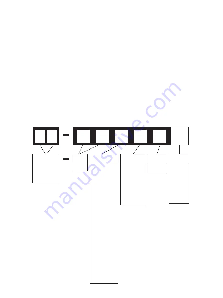
rating of the valve are shown on the serial plate. Refer to Figure
1 to identify the valve model.
3. Principle of Operation
The concept of the Camflex II valve is based on an eccentrically
rotating spherical plug contained in a free flow body design. The
plug seating surface is joined by flexible arms to a hub which
slides onto a rotating shaft. The plug is free to center itself along
the axis of the shaft. A positive seal between plug and seat is
achieved by elastic deformation of the plug arms. The chamfered
seat ring is fixed in the valve body by a threaded retainer.
The plug and shaft are rotated through an angle of 50° by a lever
linked to a powerful spring-opposed rolling diaphragm actuator.
The solid disk-type handwheel and locking hex nut, optional, are
mounted on the yoke, opposite the actuator and may be used
to manually operate the valve or as a limit stop. A threaded hole
in the opposite side of the yoke is plugged but can be equipped
with an optional cap screw and locknut, which may be inserted
as a limit stop in the other direction, or in combination with the
handwheel to lock the valve in a selected position.
Figure 1
35002 Series Numbering System
Trim Type
Design
1st
2nd
Actuator Type
1. Parallel to
pipeline, valve
closes on stem
extension.
2. Parallel to
pipeline, valve
opens on stem
extension.
3. Perpendicular
to pipeline,
valve closes on
stem extension.
4. Perpendicular
to pipeline,
valve opens on
stem extension.
5. Parallel to
pipeline, valve
closes on stem
extension.
6. Parallel to
pipeline, valve
opens on stem
extension.
7. Perpendicular
to pipeline,
valve closes on
stem extension.
8. Perpendicular
to pipeline,
valve opens on
stem extension.
Actuator Mounting
(see guide on page 3)
Body
Series
35
SB
(optional
separable
bonnet)
GR
(optional
Globe
Replacement
face to face)
2
Design
Series
1. Metal Seat
2. Soft Seat
3. Metal Seat
w/ Differen
-
tial Velocity
Trim
4. Soft Seat w/
Differential
Velocity Trim
20 Manual Actuator
35 Spring-opposed
rolling-dia
-
phragm
4th
3rd
5th
2
2nd
5
1st
3


