9 | Baker Hughes
Copyright 2020 Baker Hughes Company. All rights reserved.
M.
Connect air supply line to diaphragm case (42).
N.
Turn on air supply and check for leaks.
O.
If necessary, reposition handwheel (53) and limit stop (77),
(optional) to desired location and place valve back in service.
9.2 Body S/A Internal Parts
During a maintenance of Camflex II valve it is necessary to inspect
all the internal parts to determine if they are worn, corroded and
damaged, especially the following seating area:
– body and seat ring contact area.
– the seating surface of the plug and seat ring.
– the guide surface of the shaft and the guide bushing.
All parts which are damaged must be replaced by original spare
parts.
9.2.1 Hard Seat Lapping
Lapping is the process of working the valve sealing parts against
each other with an abrasive, to produce a close fit. To perform
the lapping operation, proceed as follows.
A.
Clean the seat ring sealing surface in the valve body and the
seat ring shoulder.
B.
Apply a small amount of fine grinding compound to the seat
ring shoulder.
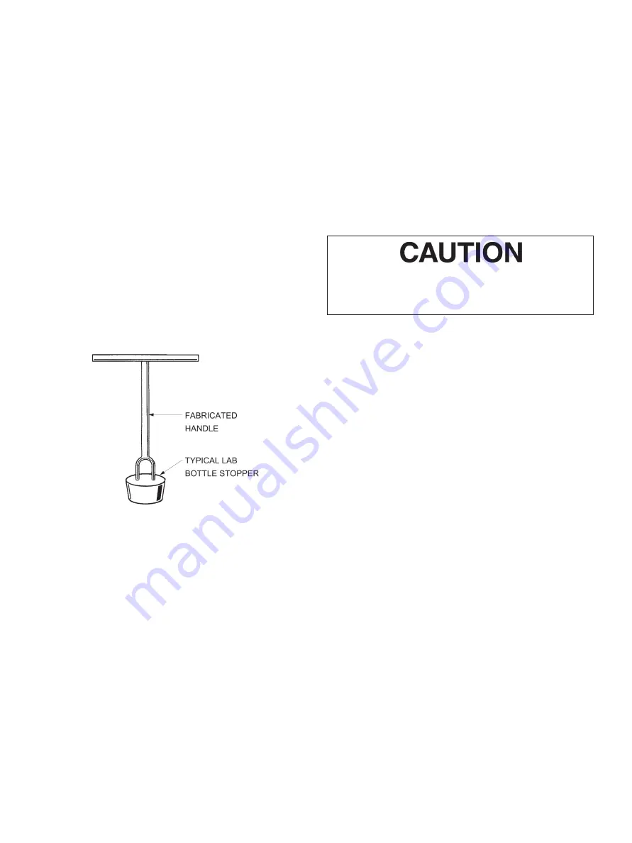
Figure 8
C.
Insert the seat ring into the body and lap lightly by rotating
the seat ring in the body, ensuring that the entire seat ring
sealing surface in the valve body is lapped. Do not rotate in
one place.
Note: Figure 8 illustrates a simple tool which may be
fabricated to facilitate this lapping operation on smaller
valves.
D.
Remove seat ring and clean thoroughly.
E.
Place seat ring on a flat surface with the seating area facing
up.
F.
Apply a small amount of fine grinding compound to the seat
ring seating surface.
G.
Lap the plug lightly against the seat ring while turning and
oscillating the plug in all directions.
H.
Clean seat ring, plug and valve body thoroughly in pre-
paration for reassembly.
9.2.2 Soft Seat
Do not lap the soft seat ring to the plug; however, the seat ring
must be lapped to the valve body. The procedure for lapping the
seat ring to the body is the same as stated in items A through D
of Section 9.2.1 on Hard Seats.
9.3 Yoke Assembly (Refer to Figures
16 and 17)
Maintenance required on the yoke (33) is limited to replacement
of the grommet (12) and the shaft bearing (8). To replace either,
the actuator must be separated from the body. (Depending on
the type of actuator used, refer to appropriate section). Insert the
grommet into the yoke with the recessed part of the grommet
towards the shaft bearing. The shaft bearing (8) is slip fit into
the yoke and is removed by pushing it out towards the grommet.
Ensure the bearing seat in the yoke is clean. The
bearing should slide in easily. Do not use excessive
force to push bearing in.
10. Reassembly Procedures
10.1 Spring Diaphragm Actuator
When the actuator has been disassembled using Section 8.2 to
reassemble the actuator, proceed as follows:
A.
Replace spring (39) in piston (43).
B.
Replace washer (44) and locknut (45).
Note: Locknut (45) must be threaded the full length of
the threads.
C.
To reassemble the diaphragm and upper diaphragm case,
refer to Section 9.1, steps E. through L.
D.
Replace locknut (46) and clevis (35).
E.
Determine correct orientation and replace actuator on yoke
and replace lockwashers (37), capscrews (36) and tighten
firmly.
F.
Refer to Section 11. for actuator stem adjustment.
10.2 Spring Diaphragm Actuator on
Body S/A (Refer to Figures 16
and 17)
After completing the required maintenance or changing valve,
actuator and yoke assembly, reassemble using the following
procedure:
A.
Determine correct valve to actuator orientation.
B.
If required, reposition body studs (28) and packing flange
studs (13).
Note: Depending on the actuator position, ensure that
the body studs (short studs) when placed through the
yoke holes will be positioned in the front of the yoke
opening for ease of accessibility.
C.
Ensure that grommet (12) and shaft bearing (8) are in the
yoke. Turn shaft so the plug is in the closed position.


