20 |
Baker Hughes
© 2020 Baker Hughes Company. All rights reserved.
XIII. Maintenance Instructions (Contd.)
Uniformly coat the disc with a small amount of lapping
compound and place it on the Lap Ring. The operation is
basically the same as the nozzle except that the disc must be
moved on the Lap Ring.
Now all parts should be cleaned. First remove grease and
sealants, then remove rust and scale. Inspect the internal parts
to ensure they are not damaged by galling. Look especially at
the rubbing surfaces of the guide and disc holder.
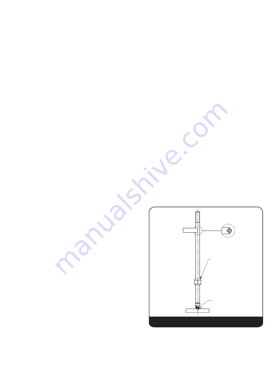
Inspect the spindle to ensure concentricity. Over-gagging is
one of the common causes of bent spindles.
Inspect the spring and washer assembly for excess clearance
[greater than .031” (0.79 mm)] and inspect the bearing surfaces
for galling.
1. Between the upper spring washer and the adjusting screw
2. The lower spring washer and the spindle shoulder
3. Spring - look for corrosion pits. Replace the spring if
severe corrosion or pitting is present. If the spring has
been in service a long time, measure the free length of the
spring. Contact Baker Hughes and give this dimension, the
spring number, and the valve set pressure to obtain their
recommendations.
On all disc holders, inspect the bearing surface between the
spindle pocket of the disc holder.
Inspect all bearing parts for concentricity, apply a very thin layer
of Clover 3A grinding compound to the actual bearing surfaces,
and grind together to determine if smooth, uninterrupted
contact is made. If grinding does not restore the original
condition or very close to it, then the parts should be replaced.
Spherical surfaces should have a 63 RMS or better surface
finish and their radius must be continuous. Each corresponding
bearing surface should be conical and smooth with a 63 RMS
or better surface finish. All traces of lapping compound must be
carefully and totally removed prior to reassembly.
A surface finish comparator is required to obtain these
readings. See Maintenance Tools and Supplies on Section XX.
The bellows (if present) should be visually inspected and
perhaps reassembled to the disc holder with a good gasket,
filled with water, and allowed to set for an hour or two to show
any leakage. At conclusion, if a successful test, then dump the
water and remove the gasket and allow the bellows to dry out.
(Make sure bellows is dry when valve is reassembled).
If conventional valve with eductor tube, push a wire through the
tube to check for plugging.
Nozzle - The nozzle seating surface must be inspected for
nicks, cuts or grooves. Minor steam cuts can be lapped out.
See dimensions in (Figure 19) and Tables 3 and 4.
Thermodisc™ - If surface defects cannot be lapped out, the
disc must be replaced. If after lapping, “A” in (Figure 16 in
Section XIII) is less than “A min.” (Table 1), replace the disc.
Adjusting Ring - The adjusting ring must have undamaged
threads. Both surfaces “A” and “B” must be undamaged (see
Figure
20).
Adjusting Ring Pin - Pin must be inspected to ensure that it is
long enough to keep the Adjusting Ring from turning yet without
touching the bottom of the notch (See Figure
20).
Gasket Surfaces - All gasket surfaces should be inspected for
cleanliness and be without radial scratches. Be sure all pieces
of the old gasket have been completely removed.
XIV. Inspection and Part Replacement
At a 45
0
angle
an indicator reading
should not exceed
.007” (0.18 mm) runout
Ball Bearing
Top View
Figure 18: V-Block Support Setup


