18 |
Baker Hughes
© 2020 Baker Hughes Company. All rights reserved.
A. Machining of Nozzle Seat
All damaged parts, as determined by inspection, must be
replaced with the exception of the valve nozzle, which may be
machined as follows:
The nozzle seat should be machined with the nozzle
assembled in the base whenever possible. If it should be
necessary to remove the nozzle from the base, use the
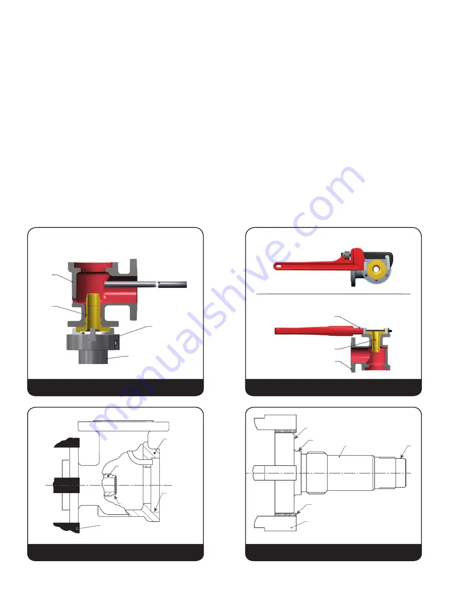
methods shown in Figure
12 or 13.
Use a hex wrench or pipe wrench as appropriate on nozzle
flange to remove nozzle from base, or use a three-jaw chuck
welded vertically to a stand bolted to the floor (see Figure
12).
Lathe set-up for machining of nozzle: grip the inlet flange of the
valve in a four-jaw independent chuck (see Figure
14).
True up the work so that the top of the nozzle at “C” and
the base surface at "B” run true within .001" (0.03 mm) on
indicator.
If the nozzle has been removed, grip the nozzle in a fourjaw
independent chuck using a piece of soft material such as
copper or fiber between the jaws and the nozzle as shown at
“A” (Figure 15).
True up the nozzle so that the surfaces marked “B”, “C” and “D”
run true within .001" (0.03 mm). on indicator.
Thermodisc™: because of the critical shape of the disc,
because of the critical shape of the disc, Baker Hughes does
not recommend machining of the disc. However, careful
lapping may be done so long as dimensions in Figure 16 and
Table 1 are maintained.
XIII. Maintenance Instructions
Base
Nozzle
3 Jaw Chuck
Chuck Stand
8' (2.4 m)-10' (3 m)
Long Rod or
Heavy Pipe
Base
Nozzle
Pipe Wrench
View From Top
View From Side
A
Chuck Jaw
Nozzle
C
B
D
Chuck Jaw
B
C
Base
Nozzle
Figure 12: Loosening the Nozzle from the Base
Figure 13: Removing the Nozzle from the Base
Figure 14: Lathe set-up for machining of nozzle
Figure 15: Nozzle Positioned in a Jaw


