Consolidated 1900/P Series Safety Valves Instruction Manual
| 25
© 2020 Baker Hughes Company. All rights reserved.
8. Apply lubricant sparingly to the inside conical end of the
spindle.
9. a) For all conventional and H thru T bellows valves,
place spindle in disc holder assembly, thread in all
the way, and be sure spindle feels “free”.
b) For bellows D through G valves, a ring type retainer
is used. Place the spindle retainer ring on the spindle
below the enlargement prior to installing the spindle
into the disc holder assembly, and snap the ring
into the internal groove at the top of the disc holder
(Figure
1) using an awl.
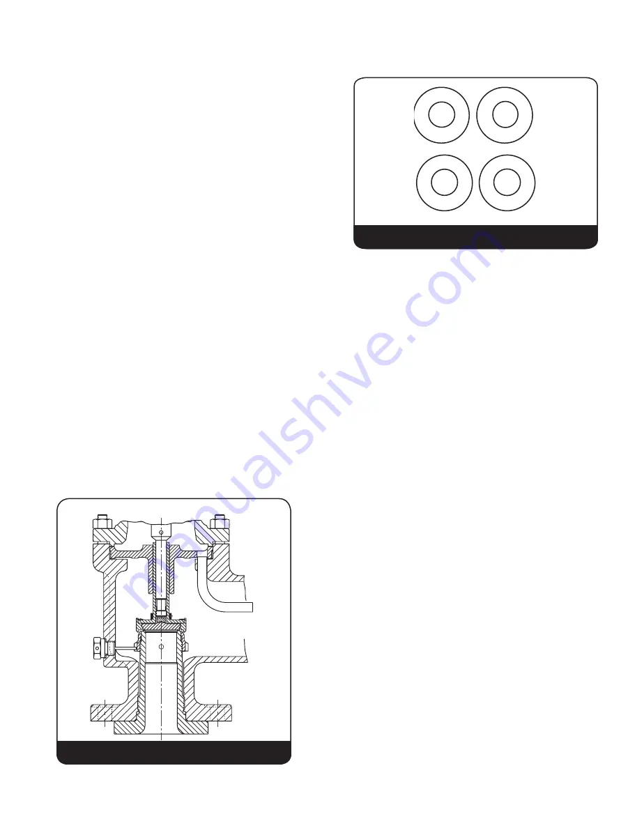
10. Place proper guide gasket in the base. If conventional
valve, use metal gasket and if bellows valve, use soft
(non-asbestos) gasket.
11. Install the spindle/disc holder assembly and guide by
gently lowering into the valve base. Take care to align
the hole(s) in the guide over the extended end of the
eductor tube(s), refer Figure
24.
Note:
Bellows valves do not have an eductor tube.
12. Apply a small quantity of lubricant to the spring washer
bearing surface of the spindle. Place the spring
assembly on the spindle.
13. Place bonnet gasket in the base prior to installing the
bonnet. Uniformly tighten the bonnet stud nuts using the
pattern shown in Figure
25.
14. With the adjusting screw lock nut assembled near the top
of the adjusting screw, apply a small quantity of lubricant
to the spherical end of the adjusting screw and also
lubricate the threads. Thread the adjusting screw into the
bonnet until it contacts the spring washer.
15. When compressing the spring, hold the spindle with
Vise-Grip
®
pliers to prevent the spindle from turning in
the disc holder. Turn the adjusting screw clockwise until
the original distance between the end of the spindle and
the top the adjusting screw is obtained. This method of
compressing the spring will approximately re-establish
the original set pressure. This is approximate - the valve
must be reset for the required pressure.
16. Restore the adjusting ring to its original position with
reference to the disc holder as recorded, and replace
the adjusting ring pin using a new gasket. If the original
position of the ring is not known, position the ring in
accordance with Table
11.
Be sure the ring pin enters the notch in the ring but
does not bind the ring. The ring should feel free after
the pin has been installed. If necessary, cut the pin to
the needed length or replace the pin (see Figure
20).
17. The valve is now ready for setting and testing.
B. Checking Lift on D and E
Valves
It is important to check the length of the lift restricting
washer on all D and E “restricted lift” valves after servicing
or replacement of parts. This is necessary to ensure the
reliability of the nameplate capacity.
Notes:
A. The limit washer must be chamfered to clear disc holder
fillet radius.
B. For bellows valves, the limit washer must also be
chamfered on the lower O.D. as shown in Figure 26.
XV. Reassembly (Contd.)
Eductor Tube is not
universal (see Fig. 1)
Figure 25
1
4
2
3
4
Holes
1
4
6
2
5
3
6
Holes
5
1
4
8
6
2
7
3
8
Holes
7
5 1
10
4
11
6
8 2
12
9
3
12
Holes
1
4
2
3
4
Holes
1
4
6
2
5
3
6
Holes
5
1
4
8
6
2
7
3
8
Holes
7
5 1
10
4
11
6
8 2
12
9
3
12
Holes
Figure 24


