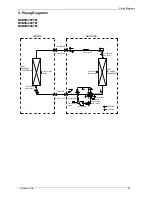
Piping Diagrams
Outdoor Units
27
3.
Piping Diagrams
BSBSIC36CT
M
BSBSIC48CT
M
BSBSIC60CT
M
Throttle orifice
LIQUID SIDE
GAS SIDE
HEAT
EXCHANGE
(EVAPORATOR)
HEAT
EXCHANGE
(CONDENSER)
Compressor
2-WAY VALVE
3-WAY VALVE
4-WAY VALVE
COOLING
HEATING
T2 Evaporator
temp. sensor
T1 Room temp.
sensor
Accumulator
T5 Discharge
temp. sensor
High pressure
switch
Low pressure
switch
INDOOR
OUTDOOR
T3 Condenser
temp. sensor
T4 Ambient
temp. sensor
Содержание BSBSI36CTM
Страница 5: ...External Appearance General Information 3 2 External Appearance 2 1 Indoor Units Duct ...
Страница 14: ...Service Space 12 Duct Type 3 Service Space Ensure enough space required for installation and maintenance ...
Страница 15: ...Wiring Diagrams 13 4 Wiring Diagrams BSBSIE36CTM BSBSIE48CTM BSBSIE60CTM ...
Страница 22: ...Field Wiring 20 Duct Type 10 Field Wiring ...
Страница 25: ...Dimensions 23 Outdoor Units Model Unit mm W D H W1 A B BSBSIC60CTM 952 415 1333 1045 634 404 ...
Страница 28: ...Wiring Diagrams 28 Outdoor Units 4 Wiring Diagrams BSBSIC36CTM BSBSI48CTM BSBSIC60CTM ...
Страница 42: ...Installation Installation 43 ...
Страница 82: ...Troubleshooting Electrical Control System 85 ...

