


REPAIR/REPLACEMENT AND UPGRADE
DISASSEMBLY OF TYPE STT03E TERMINAL CASE
7 - 2
WBPEEUI110501A0
8. Avoid static charges during repair. Make sure circuit board is thoroughly
clean around its leads but do not rub or clean with an insulating cloth.
NOTE:
An antistatic kit (field service kit, Bailey-Fischer & Porter part
number 1948385 1) is available for personnel working on devices con-
taining MOS components. The kit contains a static-dissipative work sur-
face (mat), a ground cord assembly, wrist bands and alligator clip.
DISASSEMBLY OF TYPE STT03E TERMINAL CASE
Complete the following procedure prior to performing the other procedures
of this section.
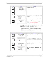
1. Turn the power off by pressing
on the keypad.
2. Place the Type STT03E terminal on a table or smooth surface with the
keypad facing down.
3. Remove the four screws from the lower case of the terminal.
4. Carefully lift the lower case off the PC board.
5. Grasp the PC board by the edges and turn it over so the components on
the board are facing up (Fig.
6. Carefully disconnect the keypad connector strip from the PC board.
This will allow the PC board to lie flat next to the upper case
assembly.
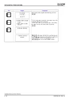
REPLACING TYPE STT03E TERMINAL EPROM (FIRMWARE UPGRADE)
The EPROM chip stores the operating software (firmware) of the Type
STT03E terminal (Fig.
). When needed, software revisions are made to
the firmware and can be obtained by customers (refer to
Figure 7-1. Internal Component Locations
OFF
TP30228A
NVRAM
NOTCHED
SIDE OF
EPROM
NVRAM
ORIENTATION
MARK
EPROM
STANDOFF
SCREW
BATTERY
HOUSING
BATTERY
HOUSING
CLIPS
KEYPAD
CONNECTOR
STRIP
UPPER HALF
OF CASE
LOWER HALF
OF CASE
PC BOARD


