20
20
Rotating/Replacing Lower Die
Note: Never install or use dies that are cracked, chipped, or otherwise damaged.
Make sure dies are the correct size and type to reduce the risk of overload.
1. Raise the ram to the top position and unplug the machine from the power supply.
2. Loosen the four adjusting bolts (A) (two in front and two in the back) which align and secure
the die to the table.
3. Carefully rotate or remove the die on/from
the table. Do not drop the die as this will
cause damage and or injury.
4. With the desired bending groove selected,
center the die across the width of the table
and visually align the desired die groove to
the upper die.
5. Connect power to the machine and start the
pump.
6. Place the selector switch in JOG mode.
7. Verify that hands and all tools and materials
are clear and slowly lower the top die gently
into the selected V-groove of the bottom die
to position it.
8. When the top die is placing light pressure on the lower die in the desired groove, stop the
machine and disconnect power.
9. Evenly tighten the adjusting bolts (A). Take care not to over tighten the back bolts for
example which would place forward pressure on the lower die and cause a misalignment
when the upper die is retracted.
10. When the adjustment bolts are evenly tight and securing the lower die in position, tighten
the jam nuts to lock the bolt positions.
WARNING:
Always keep hands and fingers from between the dies.
The dies supplied with the press are heavy. Have an assistant and a suitable lifting
device available. DO NOT try and remove by yourself.
A
Содержание BP-3142NC
Страница 3: ......
Страница 16: ...13 13 GETTING TO KNOW YOUR MACHINE A B C D E G H I F J K L M N O ...
Страница 24: ...21 21 Punch and Die Specifications ...
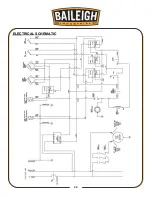
Страница 28: ...25 25 ELECTRICAL SCHEMATIC ...
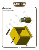
Страница 29: ...26 26 PARTS DIAGRAMS Base Assembly Parts Diagram ...
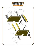
Страница 30: ...27 27 Main Frame Assembly Parts Diagram ...
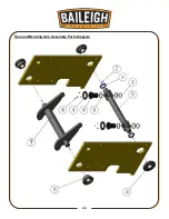
Страница 31: ...28 28 Trunnion Bending Arm Assembly Parts Diagram ...
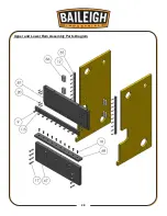
Страница 32: ...29 29 Upper and Lower Ram Assembly Parts Diagram ...
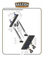
Страница 33: ...30 30 Back Stop Slide Shaft Assembly Parts Diagram ...
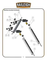
Страница 34: ...31 31 Back Stop Assembly Parts Diagram ...
Страница 35: ...32 32 Chain Tensioner Assembly Parts Diagram ...
Страница 36: ...33 33 Cylinder Assembly Parts Diagram ...
Страница 37: ...34 34 Travel Limit Assembly Parts Diagram ...
Страница 38: ...35 35 Linkage Assembly Parts Diagram ...
Страница 39: ...36 36 Cross Plate Assembly Parts Diagram ...
Страница 40: ...37 37 Tooling Assembly Parts Diagram ...
Страница 46: ...43 43 NOTES ...
Страница 47: ...44 44 NOTES ...


