10
10
TRANSPORTING AND LIFTING
Follow these guidelines when lifting:
•
Always lift and carry the machine with the lifting holes provided at the top of the machine.
•
Use lift truck and lift equipment such as straps, chains, capable of lifting 1.5
– 2 times the
gross weight of the machine and any packaging.
•
Use a fork lift with sufficient lifting capacity and forks that are long enough to reach the
complete width of the machine.
•
Approaching the machine from the side, lift the machine on the frame taking care that there
are no cables or pipes in the area of the forks.
•
A forklift is the best way to remove machine from the skid, picking up underneath the
cabinet.
•
Take proper precautions for handling and lifting.
•
Remove the securing bolts that attach the machine to the pallet.
•
Make sure the machine is balanced. While transporting, avoid rough or jerky motion, and
maintain a safe clearance zone around the transport area.
•
Locate the machine where it is to be installed, and lower slowly until it touches the floor.
•
Level the machine so that all the supporting feet are taking the weight of the machine and no
rocking is taking place.
CAUTION:
Lifting and carrying operations should be carried out by
skilled workers, such as a truck operator, crane operator, etc. If a crane is used to lift
the machine, attach the lifting chain carefully, making sure the machine is well
balanced. Choose a location that will keep the machine free from vibration and dust
from other machinery. Keep in mind that having a large clearance area around the
machine is important for safe and efficient working conditions.
CAUTION:
This machine is extremely top heavy. Failure to take proper
lifting precautions may cause the machine to tip causing severe damage and
possible injury or death to any person that the tipping machine contacts.
Содержание BP-3142NC
Страница 3: ......
Страница 16: ...13 13 GETTING TO KNOW YOUR MACHINE A B C D E G H I F J K L M N O ...
Страница 24: ...21 21 Punch and Die Specifications ...
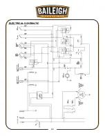
Страница 28: ...25 25 ELECTRICAL SCHEMATIC ...
Страница 29: ...26 26 PARTS DIAGRAMS Base Assembly Parts Diagram ...
Страница 30: ...27 27 Main Frame Assembly Parts Diagram ...
Страница 31: ...28 28 Trunnion Bending Arm Assembly Parts Diagram ...
Страница 32: ...29 29 Upper and Lower Ram Assembly Parts Diagram ...
Страница 33: ...30 30 Back Stop Slide Shaft Assembly Parts Diagram ...
Страница 34: ...31 31 Back Stop Assembly Parts Diagram ...
Страница 35: ...32 32 Chain Tensioner Assembly Parts Diagram ...
Страница 36: ...33 33 Cylinder Assembly Parts Diagram ...
Страница 37: ...34 34 Travel Limit Assembly Parts Diagram ...
Страница 38: ...35 35 Linkage Assembly Parts Diagram ...
Страница 39: ...36 36 Cross Plate Assembly Parts Diagram ...
Страница 40: ...37 37 Tooling Assembly Parts Diagram ...
Страница 46: ...43 43 NOTES ...
Страница 47: ...44 44 NOTES ...


