background image

Operation 

H-SEM 

14 

Instruction 3015-4584


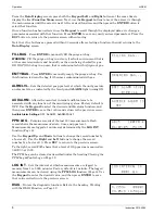
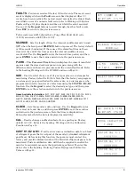
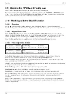
R134A CALFACTOR 
     1.000 

CUSTOM CAL K^1 
    xxxx.xxx 

CUSTOM CAL K^2 
    yyyy.yyy 

CUSTOM CAL K^3 
    zzzz.zzz 

3.12   Entering Custom Refrigerant Calibration Values 

In addition to the pre-programmed refrigerant gases available for selection, 

a custom gas can be added by using the 

CUST K1, K2 & K3 

function. 

Before using this function, the user must contact the factory and provide 

information about the gas to be monitored. The factory will then supply 

values for K1, K2, and K3, which are the coefficients of a polynomial 
equation that represent the calibration curve of the custom gas. 
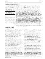
From the 

Data Display

 screen, press both


the

 Keypad


Left

 and 

Right


buttons at the same time to display the first 

Function Menu

 screen. Next, 

use the 

Keypad

 buttons to move the arrow (>) until it points to the 

CUST 

K1

 function, and then press 

ENTER

 to display the 

CUSTOM CAL K^1


screen. Use the 

Keypad

 buttons to enter the 1

st

 coefficient value (K1) as received from the factory. Press 

ENTER

 to store this value. Repeat this procedure to enter the values for K2 and K3. 

Select the custom gas for monitoring by using the 

GAS 

function (Page 9). 

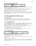
3.13   Working with the Calibration Function 

If greater than standard accuracy is desired, the factory’s default calibration factor of 1.000 may be 
adjusted by performing the calibration procedure as described below, and then selecting the monitor’s 

CAL 

function to enter the new calibration factor. 

IMPORTANT:


Changing the calibration factor will VOID the factory calibration. Typically, the monitor will 

remain within the factory-calibrated accuracy indefinitely and no calibration is required. Complex software 

algorithms adjust for temperature drift, IR source aging, and pressure changes in order to keep the unit 

within factory accuracy specifications. 


3.13.1 Calibration Procedure 

The calibration factor is determined by sampling a known concentration of R-134A refrigerant gas. A 

cylinder of a certified calibration gas must be used to ensure that the gas sample is a known concentration 
at ambient conditions. A minimum sample size of 5 liters is required.   
Calibration is best performed at or near full scale (1,000 ppm). It can, however, be done at any 

concentration and ideally in the range where maximum accuracy is desired down to, but not below, 
100 ppm. 
The monitor should be operating for at least one hour prior to performing a calibration.   
Prepare the monitor for sampling by using the 

CAL 

function to set the calibration factor to 1.000. Also, 

use the 

LOG INT 

function to set the log interval to 1 minute. 

With the monitor operating normally, connect the gas-sample bag directly to the gas-inlet port and allow 
the monitor to sample the entire bag. When sampling is complete, view the logged ppm values using the 

PPM LOG 

function.  If the bag was large enough for multiple samples, average the most stable ones. The 

new calibration factor is computed by dividing the known gas concentration value by the measured value. 
Typically this number will be between 0.95 and 1.05.  Use the 

CAL 

function as described below to enter 

the new calculated calibration factor 

3.13.2  Adjusting Calibration Factor 

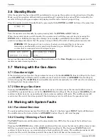
From the 

Data Display

 screen, press both


the

 Keypad


Left

 and 

Right


buttons at the same time to display the first 

Function Menu

 screen. Next, 

use the 

Keypad

 buttons to move the arrow (>) until it is next to the 

CAL


function, and then press 

ENTER

 to display the 

Calibration

 screen. 

With the 

Calibration

 screen displayed, use the 

Keypad

 buttons to enter the new calibration factor. Press 

ENTER

 to save this value.

Содержание H-SEM

Страница 1: ...H SEM Halogen Safe Entry Monitor Instruction 3015 4584 Operation Maintenance Rev 0 November 2005 Product Leadership Training Service Reliability...

Страница 2: ...ACCEPTED IN LIEU OF I ANY AND ALL OTHER WARRANTIES EXPRESS OR IMPLIED INCLUDING WITHOUT LIMITATION THE IMPLIED WARRANTIES OF MERCHANTABILITY AND FITNESS FOR A PARTICULAR PURPOSE AND II ANY OBLIGATION...

Страница 3: ...4 2 Charging the Battery 6 3 5 Display Screens 7 3 5 1 Initial Power Up 7 3 5 2 Filling the Purge Air Bag 7 3 5 3 Data Display Screen 7 3 5 4 Function Screens 7 3 6 Standby Mode 10 3 7 Working with t...

Страница 4: ...tents H SEM ii Instruction 3015 4584 4 MAINTENANCE 15 4 1 Disassembly 15 4 2 Internal Particulate Hydrophobic Filter Replacement 16 5 PARTS AND SERVICE 17 5 1 Replacement Parts 17 5 2 Service Centers...

Страница 5: ...d associated with the use of this equipment It calls attention to a procedure practice or condition or the like which if not correctly performed or adhered to could result in personal injury or death...

Страница 6: ...ting due to changes in air pressure Deflate the bag by selecting the EMTYBAG function as described on Page 8 1 7 Unpacking and Initial Checks Your Halogen Safe Entry Monitor was carefully inspected at...

Страница 7: ...e current gas level and the peak gas level detected in that area on its front panel LCD The monitor retains a log of previous readings that can be easily accessed at a later time for analysis Front pa...

Страница 8: ...onds Temperature Drift 1 5 ppm per C between purge cycles System Noise Less than 40dB A at 10 ft 3 m Operating Temp 32 to 122 F 0 to 50 C Ambient Humidity 5 to 90 RH non condensing Altitude Limit 6 56...

Страница 9: ...h air that is of the same temperature and relative humidity as the area being checked for gas DO NOT fill the purge air bag in an area that is contaminated with refrigerant gas After the purge air bag...

Страница 10: ...le alarm will reactivate if the fault condition is not cleared within the time period set by the SILENCE function Page 9 Both the FAULT light and audible alarm will automatically turn OFF after the ca...

Страница 11: ...ill automatically resume normal operation 3 5 3 Data Display Screen During normal operation the Data Display screen shows when the monitor is performing the following two functions MEASURE indicates t...

Страница 12: ...g ON AUDALRM Allows the monitor s internal audible alarm to be associated with any function of the monitoring system Factory default is OFF Use the Keypad to select the desired audible alarm function...

Страница 13: ...pe as specified on the sales order or a custom gas can be programmed into the monitor at a later time using the CUST K1 K2 K3 function Use the Keypad to select the desired gas type and then press ENTE...

Страница 14: ...panel ALARM light will flash and the audible alarm if activated refer to AUDALRM function Page 8 will start beeping The ALARM light and audible alarm will automatically turn OFF once the detected gas...

Страница 15: ...eme temperatures Use the DIAG function to check the Box Temperature 0002 Bench Temperature Fault Optical bench is outside normal operating range or IR detector has failed Check that the monitor is not...

Страница 16: ...the First Diagnostic screen the user can toggle between displaying Bench Voltage Detector Temperature and Noise Box Temperature by pressing the Keypad Right button Bench Voltage This is the current pe...

Страница 17: ...e Data Display screen press both the Keypad Left and Right buttons at the same time to display the first Function Menu screen Next use the Keypad buttons to move the arrow until it points to the P CHK...

Страница 18: ...temperature drift IR source aging and pressure changes in order to keep the unit within factory accuracy specifications 3 13 1 Calibration Procedure The calibration factor is determined by sampling a...

Страница 19: ...l chassis as follows Items Required Medium Phillips head screwdriver Procedure 1 Remove monitor and its battery pack from the soft carrying case 2 Unplug battery pack from monitor 3 Remove a total of...

Страница 20: ...1 2 See illustration below and locate the internal particulate hydrophobic filter 3 Pull off tubing from both ends of filter and remove filter from instrument 4 Attach tubing to new filter being sure...

Страница 21: ...rvice 5 1 Replacement Parts Item Description Part Number Halogen Safe Entry Monitor 3015 4484 External Filter 3015 3420 Internal Particulate Filter 07 1654 Battery Pack Charger 3015 4654 Battery Charg...

Страница 22: ...il help bacharach inc com Canada Bacharach of Canada Inc 250 Shields Court Unit 3 Markham Ontario L3R 9W7 Canada Phone 905 470 8985 Fax 905 470 8963 Email bachcan idirect com M xico Bacharach de M xic...

Страница 23: ...H SEM Parts and Service Instruction 3015 4584 19 Notes...

Страница 24: ...1 Hunt Valley Circle New Kensington PA 15068 PH 724 334 5000 Toll Free 800 736 4666 FAX 724 334 5001 Website www bacharach inc com E mail help bacharach inc com Printed in U S A Registered Trademark o...

Отзывы: