Assembly
8
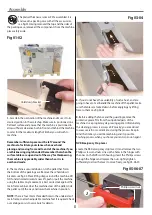
The planer Thicknesser comes 95% assembled. It is
enclosed in a packing case with all the accessories,
see fig 01. Having removed the top and the sides of
the packing case, remove all the components from the machine,
place safely aside.
Fig 01-02
1. Ascertain the orientation of the machine and move it to its
desired position in the workshop. Make sure its positioned on a
flat level surface and ensure that the machine is positioned to
allow sufficient clearance both in front and behind the machine
to cater for the maximum length of timber you will wish to
machine.
Remember sufficient space must be left ‘around’ the
machine to facilitate your stance when overhand
planing and moving from end to end of the machine if you
are thicknessing single handed. Remember that when the
surface tables are up and out of the way’ for thicknessing,
the machine is appreciably wider than when it is in
overhand mode.
2. The machine is secured down on to the pallet that forms
the bottom of the packing case. Remove these ‘hold down’
brackets, see fig 02. Place lifting straps around the machine, DO
NOT under normal circumstances lift, push or pull the machine
using the tables. Any movement is best carried out against the
main frame cabinet. Hoist the machine clear of the pallet, slide
the pallet out of the way and lower the machine in position.
NOTE: There is four 10mm threaded holes to the underside of
main frame, to attach adjustable machine feet if required. Check
our catalogue or vist our website for details.
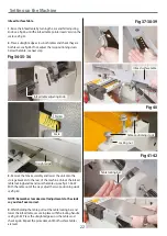
Fig 03-04
3. If you do not have the availability of such a hoist, and are
going to have to ‘manhandle’ the machine off the pallet; make
sure the tables are locked down before applying any lifting
force to them, see fig 03-04.
4. Before adding the fence and the guarding remove the
protective grease film from the unpainted parts of the
machine. Use a proprietary de-greasing agent. Unfortunately,
this cleaning process is always a bit ‘mucky’, you are advised
to wear overalls or coveralls etc., during the process. Keep in
mind the timber you will be machining and its possible
finishing process, when you choose your anti-corrosion agent.
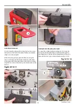
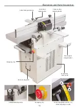
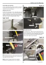
NVR Emergency Stop Lever
Locate the RED emergency stop lever (J) and remove the two
Phillips screws and nuts. Line up the holes in the hinges with
the ones on the NVR switch housing, insert the Phillips screws
through the hinges and replace the nuts. Lightly tighten
sufficiently to allow the lever to move freely, see fig 05-06-07.
Fig 05-06-07
J
Phillips screw/nut
Hold down bracket
Содержание AT260PT
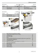
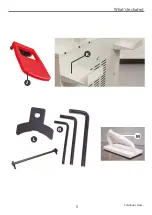
Страница 4: ...What s Included 4 C D F E G H I ...
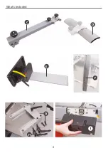
Страница 5: ...What s Included 5 L N K J M Continues Over ...
Страница 34: ...Exploded Diagrams Lists 34 DIAGRAM A AT260PT AT260SPT PlanerThicknesser ...
Страница 36: ...Exploded Diagrams Lists 36 AT260PT AT260SPT PlanerThicknesser DIAGRAM B ...
Страница 38: ...Exploded Diagrams Lists 38 AT260PT AT260SPT PlanerThicknesser DIAGRAM C ...
Страница 40: ...Exploded Diagrams Lists 40 AT260PT AT260SPT PlanerThicknesser DIAGRAM D ...
Страница 42: ...Exploded Diagrams Lists 42 AT260PT AT260SPT PlanerThicknesser DIAGRAM E ...
Страница 46: ...Exploded Diagrams Lists 46 DIAGRAM A AT310SPT PlanerThicknesser ...
Страница 48: ...Exploded Diagrams Lists 48 DIAGRAM B AT310SPT PlanerThicknesser ...
Страница 50: ...Exploded Diagrams Lists 50 DIAGRAM C AT310SPT PlanerThicknesser ...
Страница 52: ...Exploded Diagrams Lists 52 DIAGRAM D AT310SPT PlanerThicknesser ...
Страница 54: ...Exploded Diagrams Lists 54 DIAGRAM E AT310SPT PlanerThicknesser ...
Страница 58: ...Spiral Cutter Block Diagram 58 Spiral Cutter Block 10 Inch Spiral Cutter Block 12 Inch ...
Страница 59: ...Wiring Diagrams 59 AT260PT AT260SPT DIAGRAM AT310SPT DIAGRAM ...

