Assembly
10
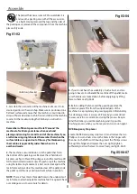
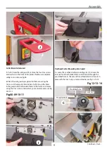
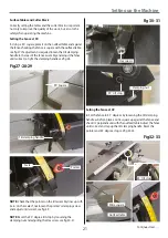
Fig 15
2. Locate the cutter block guard (D). Loosen the locking knob
on top of the mounting plate holder on the mounting arm (C).
Slot the cutter block guard through the mounting plate and
tighten the locking knob, see fig 15.
Mounting the Fence
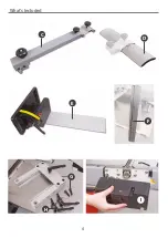
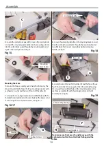
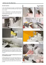
To mount the fence assembly put to hand the following: The
fence tilt assembly (E), fence (F), fence mounting bracket with
cap head screws (G) and the two lift and shift handles (H).
1. Line up the mounting bracket (G) pre-drilled holes with the
threaded holes mid table to the rear of planer thicknesser and
secure using the two cap head screws, see fig 16-17.
Fig 16-17
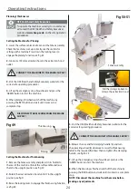
2. Loosen the clamping handle on the mounting bracket, insert
the tilt assembly base plate (E) through the mounting bracket
(G) sufficiently for the next step. Lightly tighten clamping
handle, see fig 18.
Fig 18
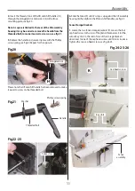
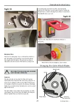
3. Locate the two lift and shift handles (H) and the fence (F),see
fig 19. Position the fence up against the tilt assembly housing
(E). Line up the pre-drilled holes in the mounting plate to the
rear fence assembly (F) with the elongated slots in the tilt
assembly housing (E).
Fig 19
Note: make sure the fence is the right way up with the
machined cutout for the cutter block flush against the
tables.
D
Mounting
plate holder
G
Cap head screws
Hex key
Clamping handle
E
Base plate
G
H
F
Mounting plate
Tilt assembly housing
C
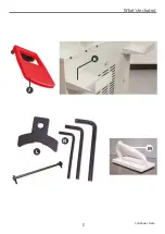
Содержание AT260PT
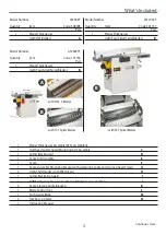
Страница 4: ...What s Included 4 C D F E G H I ...
Страница 5: ...What s Included 5 L N K J M Continues Over ...
Страница 34: ...Exploded Diagrams Lists 34 DIAGRAM A AT260PT AT260SPT PlanerThicknesser ...
Страница 36: ...Exploded Diagrams Lists 36 AT260PT AT260SPT PlanerThicknesser DIAGRAM B ...
Страница 38: ...Exploded Diagrams Lists 38 AT260PT AT260SPT PlanerThicknesser DIAGRAM C ...
Страница 40: ...Exploded Diagrams Lists 40 AT260PT AT260SPT PlanerThicknesser DIAGRAM D ...
Страница 42: ...Exploded Diagrams Lists 42 AT260PT AT260SPT PlanerThicknesser DIAGRAM E ...
Страница 46: ...Exploded Diagrams Lists 46 DIAGRAM A AT310SPT PlanerThicknesser ...
Страница 48: ...Exploded Diagrams Lists 48 DIAGRAM B AT310SPT PlanerThicknesser ...
Страница 50: ...Exploded Diagrams Lists 50 DIAGRAM C AT310SPT PlanerThicknesser ...
Страница 52: ...Exploded Diagrams Lists 52 DIAGRAM D AT310SPT PlanerThicknesser ...
Страница 54: ...Exploded Diagrams Lists 54 DIAGRAM E AT310SPT PlanerThicknesser ...
Страница 58: ...Spiral Cutter Block Diagram 58 Spiral Cutter Block 10 Inch Spiral Cutter Block 12 Inch ...
Страница 59: ...Wiring Diagrams 59 AT260PT AT260SPT DIAGRAM AT310SPT DIAGRAM ...

