


L
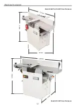
Changing the Cutter Block Blades
26
Changing the Standard Blades
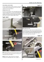
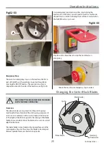
1. Remove the fence assembly, raise the two surface tables
into the upright positions to gain access to the cutter block,
see fig 56.
2. Turn the cutter block until one of the slots is in the upright
position. Using a 4mm Hex key loosen the four cap head screws
on the cutter block, thus removing the clamping effect. This
should allow the blade to ‘spring’ up, protruding clear of the
edge of the cutter block, see fig 57.
Fig 57-58
Fig 56
DISCONNECT THE MACHINE FROM THE MAINS
SUPPLY BEFORE CONTINUING!
DO NOT OVERTIGHTEN TO AVOID THE CAP HEAD
SCREWS ENDS FROM GETTING DAMAGED!
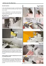
3. Carefully remove the blade and place safely aside, see fig 58.
WARNING! BE VERY CAREFUL WHEN
REMOVING THE BLADE AS IT IS EXTREMELY
SHARP.
4mm Hex key
Cap head screw
Blade
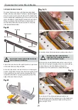
4. Remove the blade holder and lay aside. Clean the slot
housing thoroughly, remove any resin build-up, sawdust, chips
etc. Clean the blade holder and ensure the circumference of the
cutter block is cleaned thoroughly, see fig 59.
Fig 59
5. Remove the new blade from its keeper and place the old
blade in it’s place. Locate the blade setting tool (L), see fig 60.
Fig 60
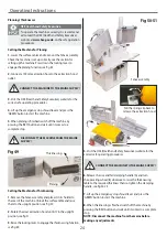
6. Introduce the blade holder, position it against the back of
the slot, introduce the blade in the front of the blade holder.
Carefully position the blade and the holder to line up with the
edge of the cutter block. Press the blade setting tool gently
down onto the blade, ensuring the locating feet are firmly
seated against the circumference of the cutter block
and the blade is against the setting recess, see fig 61-62.
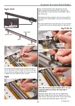
7. Holding the blade and setting tool (L) in position, tighten two
cap head screws to provide a firm clamp on the blade. Keeping
the setting tool held firmly in place tighten the remaining cap
head screws, see fig 63-64.
Blade holder
Содержание AT260PT
Страница 4: ...What s Included 4 C D F E G H I ...
Страница 5: ...What s Included 5 L N K J M Continues Over ...
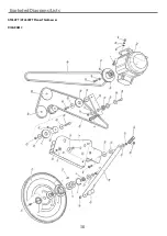
Страница 34: ...Exploded Diagrams Lists 34 DIAGRAM A AT260PT AT260SPT PlanerThicknesser ...
Страница 36: ...Exploded Diagrams Lists 36 AT260PT AT260SPT PlanerThicknesser DIAGRAM B ...
Страница 38: ...Exploded Diagrams Lists 38 AT260PT AT260SPT PlanerThicknesser DIAGRAM C ...
Страница 40: ...Exploded Diagrams Lists 40 AT260PT AT260SPT PlanerThicknesser DIAGRAM D ...
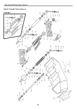
Страница 42: ...Exploded Diagrams Lists 42 AT260PT AT260SPT PlanerThicknesser DIAGRAM E ...
Страница 46: ...Exploded Diagrams Lists 46 DIAGRAM A AT310SPT PlanerThicknesser ...
Страница 48: ...Exploded Diagrams Lists 48 DIAGRAM B AT310SPT PlanerThicknesser ...
Страница 50: ...Exploded Diagrams Lists 50 DIAGRAM C AT310SPT PlanerThicknesser ...
Страница 52: ...Exploded Diagrams Lists 52 DIAGRAM D AT310SPT PlanerThicknesser ...
Страница 54: ...Exploded Diagrams Lists 54 DIAGRAM E AT310SPT PlanerThicknesser ...
Страница 58: ...Spiral Cutter Block Diagram 58 Spiral Cutter Block 10 Inch Spiral Cutter Block 12 Inch ...
Страница 59: ...Wiring Diagrams 59 AT260PT AT260SPT DIAGRAM AT310SPT DIAGRAM ...