3: I
n De
pt
h/
A
dv
an
ce
d P
ro
gr
am
m
in
g •
2
2
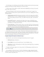
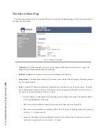
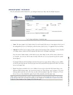
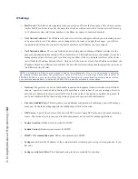
• Set Host Name / Set Source Channel:
These checkboxes allow you to choose whether the values autocal-
culated from the Node ID are used or not. Leave them checked to use them; clear them to set these values
manually.
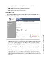
• Source Name:
Here, you can manually name the audio input of your xSelector, and it will be known
through the network by the name given in this field. Good naming practices can help users quickly identify
sources when searching the network. For example,
D07S12
is not helpful to the user who’s attempting to
locate the audio mix from a news room. The name
NewsRoomA
would be a friendlier choice!
• Destination Name:
xSelector’s front panel allows users to change the audio source that’s routed to the
unit’s output. In Livewire parlance, outputs (where sources are routed to) are called
Destinations
. Defining
a user-friendly name helps you in two ways. One, when you log into this device many months after install,
you can refer to the destination name to recall what is wired to the output.
Two other applications, for example: Remote-control software may use this name to identify the output. So
a Name of “Newsroom Router”, “Aux Select”, or some such name related to the device’s function within
your plant would be appropriate. The field may contain 16 characters or less.
• Destination Channel:
Following the Name field is the Channel field. The Channel number represents the
source to be routed to the destination. If you don’t know the number of the source to be routed, you can
press the
Browse
button immediately to the right of the text field. This opens a pop-up, which lists all the
sources available on your network. They are hyperlinked, allowing you to easily choose one by clicking on
its name.
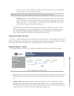
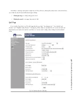
• GPIO Name
and
GPIO Channel:
The xSelector has two GPIO ports, represented by the two graphical
rows shown in this section. The first item is the Name field, which is used to identify how this resource is
being used. The next text field is referred to as the Channel field. The Channel field is where the port can be
assigned a function. There are three different ways in which a GPIO port can be used:
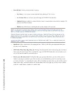
»
Port routing
In this state, the General Purpose Outputs (GPOs) of the local port will mimic the
General Purpose Inputs (GPIs) of the remote port (routing GPI logic to GPO logic). This is accom-
plished by entering in the IP address of the remote device with the GPIO port you wish to mimic
locally, followed by a Forward Slash, and then the port number of that remote port.
For example,
10 .216 .0 .121/5
would be Port 5 from the device located at IP Address 10.216.0.121,
and which supports GPIO. As a test, you could also set Port 1 of the xSelector to 127.0.0.1/1
(127.0.0.1 is known as a loopback address). This will cause the GPOs of the first port to mimic the
GPIs of the same port.
»
Channel assignment
This option assigns the local port to follow the logic associated with a se-
lected audio source; that is, the logic associated with an audio source, as defined by a console — the
GPIO commands to start and stop DAT deck, for instance, which are associated with that deck’s
audio stream.
Содержание xSelector
Страница 1: ...xSelector Installation User s Guide Manual Rev 1 January 2019 p n 1490 00105 002 TelosAlliance com...
Страница 6: ......
Страница 8: ...CAT 6 small and light yet sound and data pour forth What magic is this...
Страница 18: ...Do digital streams dream of electric DJs Just Bradbury knows...
Страница 26: ...To and fro bits flow Audio anywhere now Fingertips decide...
Страница 52: ...Elvis Costello was a true visionary Kesha not so much...
Страница 56: ...THIS PAGE INTENTIONALLY LEFT BLANK...

