Electrically connecting the ejector
O
Use protective extra low voltage (PELV) only and
provide for secure electrical isolation of the operating
voltage in accordance with EN 60204.
O
For directly connecting the ejector to the controller,
use AVENTICS connecting cables, see “Accessories”.
Make the electrical connections for the ejector as follows,
see Fig.
:
1.
Make sure the relevant system part is not under
voltage.
2.
Lay the cables so as not to bend or crush them.
3.
Connect the power supply to the pilot valves (
1
,
2
).
6
Commissioning and
Operation
CAUTION
System is under voltage during operation
Working on the system under voltage can lead to
injuries due to electric shock or damage to the
components.
O
Make sure that all relevant system parts are not under
voltage before performing work on the system.
O
Connect or disconnect plug connectors only if all
relevant system parts are without voltage.
No polarity needs to be observed when connecting
the valves.
Plugs for valves must click into place.
CAUTION
Personal injury or property damage caused
by non-compliance with specific technical rules
Operating the ejector system without power packs and
without complying with standard EN 60204 can result in
personal injuries and damage to the system and the
connected components.
O
Only operate the system using power packs with
protective extra-low voltage (PELV) and safe electric
isolation of the supply voltage in accordance with
EN 60204.
O
Do not connect or disconnect plug connectors under
voltage.
1
General functions
Setting the blow-off volume flow
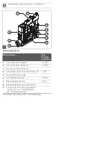
See figure
“Ejector design”.
Below the vacuum connection there is a flow control
screw for setting the blow-off volume flow.
O
Turn the flow control screw clockwise (to the right) in
order to reduce the volume flow.
O
Turn the flow control screw counterclockwise
(to the left) in order to increase the volume flow.
The flow control screw has a stop on both sides.
Commissioning
The ejector may only be commissioned after it has been
installed in the machine/system for which it is intended.
Commissioning for the first time and
recommissioning after downtime
1.
Make sure that all electrical and pneumatic
connections of the ejector are correctly connected and
are firmly fitted.
2.
Switch on the operating voltage.
3.
Switch on the operating pressure.
Operation
The ejector is actuated via the pilot valves. The blow-off
volume flow can be set via the flow control screw. See also
“Technical Data”.
WARNING
Open vacuum/exhaust air connections and vacuum
cup
Risk of injury by suctioning of eyes or other parts of the
body.
Risk of injury due to exhaust air and any other parts and
debris that may have been drawn in being emitted from
the exhaust air connection at high speed.
O
Never look into vacuum openings, neither suctioning
or not suctioning (e.g. vacuum connections or
connected vacuum cups).
O
Never look into or enter the exhaust air stream.
Do not turn the flow control screw beyond its
stops! Due to technical reasons, a minimum
volume flow of approx. 10% is always required.
The blow-off volume flow can be set to a value
between 10% and 100%.
1
AVENTICS
| ECD-BV | R412025988–BAL–001–AA | English
10


