RETE / POWER
INSERITO / ON
TAMPER
ON
UNITA' CENTRALE /
CENTRAL UNIT
AF997
SIREN AF - AF53900
26 25 24 23 22 21
EXCLUDE
ZONE
A1
ZONE
A2
ZONE
A3
ZONE
B1
ZONE
B2
ZONE
C1
ZONE
C2
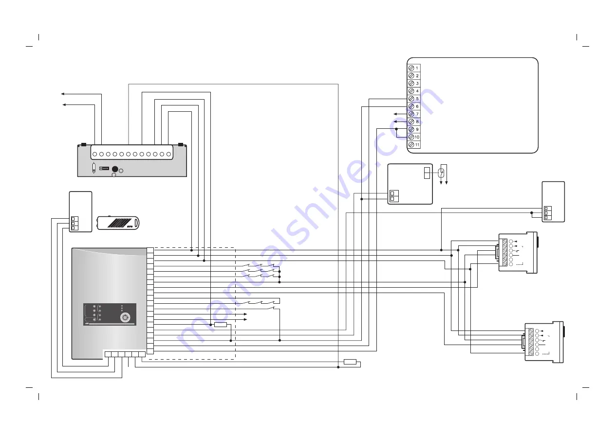
Diagram 3 – Connection to AF997
OUT
TAMPER
GND C/BAT GND IN2 GND IN1 GND IN/BL
–
+
ALIM
JP2
To the TAMPER LINE
Terminal board
AF998CE
Detector NC
contacts
Detector NC contacts
Acoustic horn connection terminal
Acoustic horn connection terminal
Flashing device connection terminal
Flashing device connection terminal
Power
Power supply –
Anti-tampering microswitch (tamper)
Anti-tampering microswitch (tamper)
Positive NC siren control
Positive NC flashing device control
Interrupted flashing device filament signal (towards GND)
Pre-alarm
signalling
device
cod.45381
Auxiliary indoor siren
Anti-tampering magnetic
contact cod. AF901
R47k
1
2
3
4
5
6
7
8
9
10
11
12
13
14
15
16
17
18
19
20
1 +
2 –
3 T
2 +
1 –
COD. AF45399
AF45360
Example of a standard detector
connection. This connection can
be performed also on zones
A1, A2, A3, C1, C2.
N
S
TAMPER
1
–
2
+
3
4
5
N.C.
6
TC
BLOCCO RELÈ
RELA
Y OUT
12V —
(10,5…14)
––
1
–
2
+
3
4
5
N.C.
6
TC
BLOCCO RELÈ
RELA
Y OUT
12V —
(10,5…14)
––
COD.
AF45342
1
2
3
AF45339
R
R
Possible technical alarm
detector NC contact. (see
note 2 and page 6)
AF45360
TAMPER
Note 1:
for connections related to
distances higher than 30 cm, use
a shielded cable (with a shield
central side earthed)
Note 2:
the wiring diagram reports
the connection of the channel 2. It
is necessary to program number 5,
6, 7, 8, using this wiring diagram
(see pag. 24).


