- 31 -
G
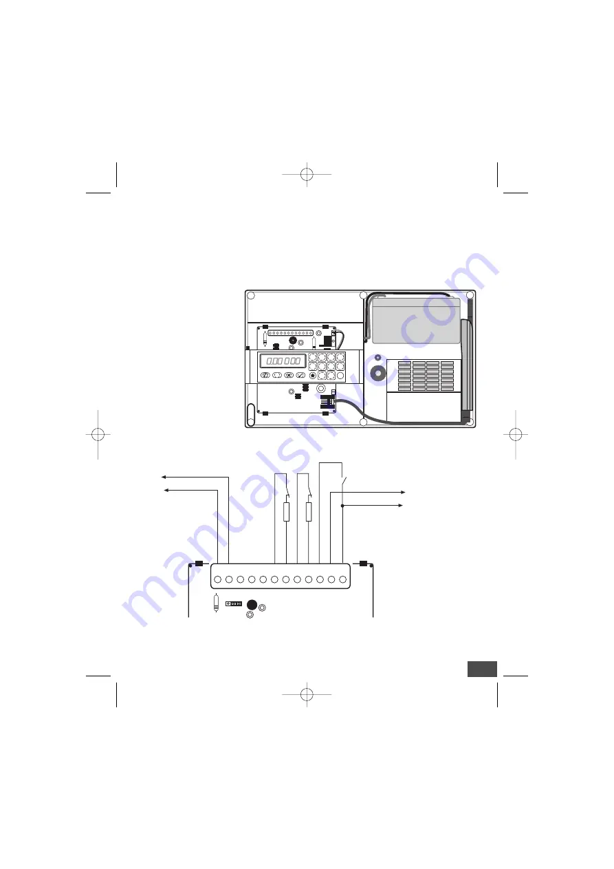
OUT TAMPER outputs
belong to a NC contact which protects against tampering and tearing. The
contact will be closed when the dialler lid is closed and its enclosure is fixed on the wall. The OUT
TAMPER terminal contact will open as soon as the lid is opened or the dialler is removed with force
from the wall. The OUT TAMPER terminals must be connected to the control panel tamper line
As an example besides
diagram 1,
refer to
diagrams 2
and
3
showing the connection between
the dialler and the
AF994
and
AF997
control panels.
INTERNAL VIEW AND
CONNECTION TO THE
PORTABLE TELEPHONE
Note:
The figure shows the
connection to the por-
table telephone
which is very fast;
just connect the con-
trol connector to the
portable telephone
base which will also
recharge the telepho-
ne battery provided.
WIRING DIAGRAMS
1)
Connection to devices having NC contact outputs.
1
2
3
4
5
6
7
8
9
0
#
F
OUT
TAMPER
GND C/BAT GND IN2 GND IN1 GND IN/BL
–
+
ALIM
R
+
_
R
JP2
To the tamper line
R = 47KOhm
TERMINAL BOARD
Power supply from the control
panel or additional power sup-
ply unit
Eventual dialler channel 2 blocking
NO contact
JP2
= The input will be balanced if the jumper is in the position (right) shown in the figure.
If it is in the left position, the positive failure alarm on terminals 5 (channel 1) or 7 (channel 2) will
start the alarm cycle.
C.410 7-06-2002 16:43 Pagina 31


